Sheet metal stamping device

A stamping device and metal plate technology, applied in metal processing, metal processing equipment, forming tools, etc., can solve the problems of reduced precision, plastic deformation, time-consuming and labor-intensive of sheet metal parts, and achieve reduced resilience, enhanced stability, Anti-shake effect

Active Publication Date: 2017-05-24
DOOR IND CO LTD CHONGQING DTOMO
View PDF8 Cites 2 Cited by
  • Summary
  • Abstract
  • Description
  • Claims
  • Application Information

AI Technical Summary

Problems solved by technology

[0003] In the process of sheet metal parts processing, the bending machine mold is mainly placed on the punching machine, and then the metal sheet is placed on the bending mold to bend the metal sheet. During the bending process, the gap between the upper and lower dies The force is applied to the sheet metal to cause plastic deformation of the sheet metal. During processing, different upper and lower dies should be selected according to the shape of the sheet metal. When the sheet metal is more complicated, the shape of the bend is also relatively Complicated, at this time, it is necessary to frequently replace the upper mold and the lower mold, and the replacement process is time-consuming and laborious; and during the processing, the workpiece will generate heat after plastic deformation, so let go of the workpiece at this time, and the workpiece The rebound performance is the strongest, which will reduce the precision of the finished sheet metal parts

Method used


Image

  • Sheet metal stamping device
  • Sheet metal stamping device
  • Sheet metal stamping device

Examples


Embodiment Construction

[0016] The present invention will be described in further detail below by means of specific embodiments:

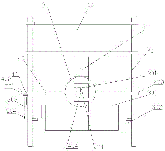
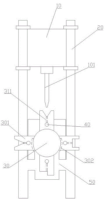
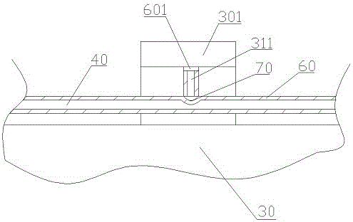
[0017] The reference signs in the drawings of the description include: hydraulic table 10, upper mold 101, frame 20, rotating shaft 30, lower mold 301, first through hole 311, fixing clip 302, handle 303, buckle 304 for fixing the handle, limit Position rod 40, laser generator 401, water inlet hole 402, water outlet hole 403, second through hole 404, machine platform 50, limit block 501, glass steel pipe 60, glass steel plate 601, and seal 70.

[0018] The embodiment is basically as attached figure 1 , attached figure 2 And attached image 3 Shown: a stamping device for sheet metal parts, including a hydraulic table 10 , a frame 20 , a machine table 50 , a hollow limit rod 40 and a fixing clip 302 sequentially connected from top to bottom. The upper end of the frame 20 is slidingly connected to the hydraulic table 10, the lower end of the frame 20 is fixedly connected...


PUM


Abstract

The invention relates to the field of machining, and particularly discloses a sheet metal stamping device which comprises a hydraulic pressure platform, a rack, sealing elements and a machine platform which are connected from top to bottom, wherein an upper die is detachably mounted on the lower surface of the hydraulic pressure platform; a rotating shaft rotatably connected with the machine platform is horizontally arranged on the machine platform; a plurality of lower dies of different models are circumferentially mounted on the rotating shaft; the lower dies are perpendicular to the rotating shaft; the sheet metal stamping device further comprises a hollow limiting rod; the limiting rod penetrates through the lower dies to be detachably connected with the machine platform; a first through hole is formed in the center of each of the lower dies; a second through hole allowing the limiting rod to be communicated with the first through holes is formed in the limiting rod; the sealing elements are fixedly mounted at the lower ends of the first through holes; a water inlet and a water outlet are formed in the limiting rod; a laser generator is arranged at the water inlet, a transparent glass reinforced plastic pipe is sleeved and connected with each of the limiting rod and the first through holes, and the outer walls of the glass reinforced plastic pipes are in contact with the inner walls of the limiting rod and the first through holes. According to the sheet metal stamping device provided by the invention, the lower dies can be quickly replaced; therefore, the processing efficiency is improved.

Description

technical field [0001] The invention belongs to the field of mechanical processing, and in particular relates to a bending device for metal plate parts. Background technique [0002] Sheet metal parts have the characteristics of light weight, high strength, low cost, and good mass production performance, and have been widely used in electronic appliances, communications, automobile industry, medical equipment and other fields. Especially in computer cases, mobile phones, and MP3 players, plate-like metal is an essential component. As the application of sheet metal parts becomes more and more extensive, the demand for sheet metal parts is also increasing, and the requirements for processing accuracy are also getting higher and higher. [0003] In the process of sheet metal parts processing, the bending machine mold is mainly placed on the punching machine, and then the metal sheet is placed on the bending mold to bend the metal sheet. During the bending process, the gap betw...

Claims


Application Information

Patent Timeline
Patent Type & Authority Applications(China)
IPC IPC(8): B21D5/02B21D37/16B21C51/00
CPCB21C51/00B21D5/002B21D5/0209B21D37/16
Inventor 万贤平
Owner DOOR IND CO LTD CHONGQING DTOMO
Why Eureka
Try Eureka