
A multifunctional lathe with tool rotation

A multi-function and tool technology, applied in the field of multi-function lathes, can solve the problems of limited processing speed, slow processing speed, insufficient speed, etc., to achieve the effect of fast cutting processing, convenient operation and simple structure

Active Publication Date: 2019-06-25
南京市溧水同发机械刀模具制造有限公司
View PDF5 Cites 0 Cited by
  • Summary
  • Abstract
  • Description
  • Claims
  • Application Information

AI Technical Summary

Problems solved by technology

[0002] CNC lathes and turning centers are high-precision, high-efficiency automatic machine tools. Equipped with multi-station turrets or power turrets, the machine tools have a wide range of processing performance, and can process straight cylinders, oblique cylinders, arcs and Various complex workpieces such as threads, grooves, and worms have various compensation functions such as linear interpolation and circular interpolation, and have played a good economic effect in the mass production of complex parts; but in CNC lathes, although it can also be The side wall of the workpiece is turned into a polygonal prism, but the processing is realized through the feed and retract of the cross seat. Since the feed and retract speed of the servo motor of the cross seat is very slow compared with the high-speed rotation speed of the spindle, there is a limit Compared with the ordinary CNC milling machine, the speed is not as good as that of the ordinary CNC milling machine; although the CNC milling machine can also process the side wall of the workpiece into polygonal columns or other special-shaped structures, the principle of milling machine processing is the whole layer It is processed one layer at a time, so its processing speed is not fast. In addition, due to the characteristics of milling, the processed surface of the workpiece is not as good as the surface quality of the turned workpiece.

Method used


Image

  • A multifunctional lathe with tool rotation
  • A multifunctional lathe with tool rotation
  • A multifunctional lathe with tool rotation

Examples


Embodiment Construction

[0031] In order to enable those skilled in the art to better understand the technical solution of the present invention, the present invention will be described in detail below in conjunction with the accompanying drawings. The description in this part is only exemplary and explanatory, and should not have any limiting effect on the protection scope of the present invention. .

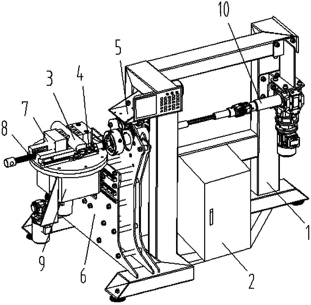
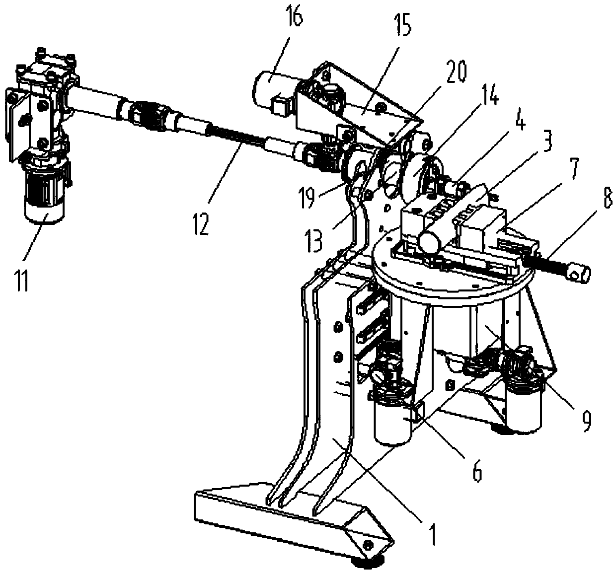
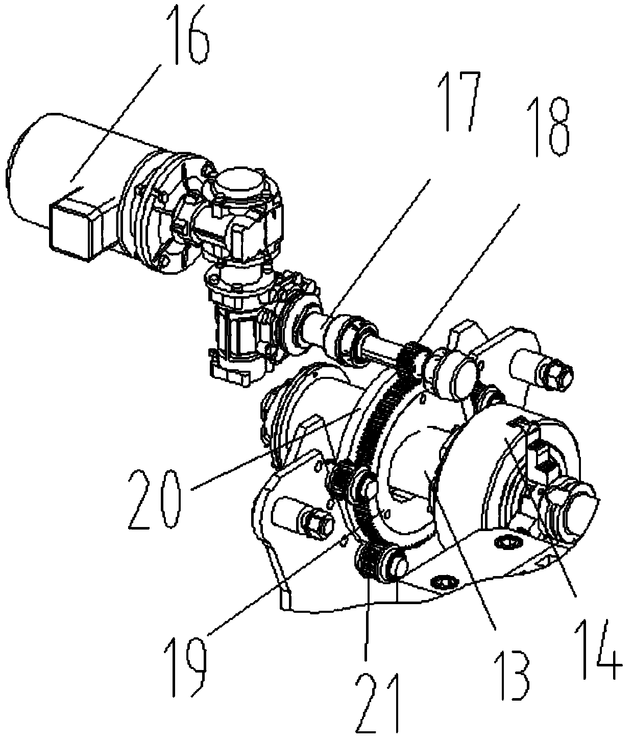
[0032] Such as Figure 1-Figure 5 As shown, the specific structure of the present invention is: a multifunctional lathe for tool rotation, which includes a frame 1 and a power distribution control box 2, and the frame 1 is provided with a tool rotating shaft 13 and a tool feeding device 10 , the tool rotating shaft 13 is equipped with a tool rotating device 5, and the end of the tool rotating shaft 13 is provided with a gripper type tool mounting disc 14, a tool 4 is installed in the tool mounting disc 14, and the tool 4 is equipped with a product carrier, the product carrier is arranged on the carrie...


PUM


Abstract

The invention relates to a multifunctional lathe with tool rotation function, comprising a frame and a power distribution box; the frame is provided with a tool rotating shaft and a tool feeding device, a tool rotator is fitted to the tool rotating shaft, an end of the tool rotating shaft is provided with a grip disc type tool mounting disc, a tool is mounted in the tool mounting disc, a product carrier is fitted to the tool, the product carrier is disposed on a carrier feeding device on the frame, the carrier and the tool have perpendicular feeding directions, and the tool feeding device, the tool rotator and the carrier feeding device are connected to the power distribution box; the tool mounting disc is mounted on the tool rotating shaft and connected to the tool rotator, the tool feeding device is fitted to the carrier that can provide forward and backward feeding, processing a product in various shapes via various techniques can be achieved through changing the tool, tool feeding can be fitted to carrier feeding, a sidewall can be turned into a polygonal prism shape, and the surface quality of a workpiece can be controlled well.

Description

technical field [0001] The invention relates to the field of mechanical processing equipment, in particular to a multifunctional lathe with tool rotation. Background technique [0002] CNC lathes and turning centers are high-precision, high-efficiency automatic machine tools. Equipped with multi-station turrets or power turrets, the machine tools have a wide range of processing performance, and can process straight cylinders, oblique cylinders, arcs and Various complex workpieces such as threads, grooves, and worms have various compensation functions such as linear interpolation and circular interpolation, and have played a good economic effect in the mass production of complex parts; but in CNC lathes, although it can also be The side wall of the workpiece is turned into a polygonal prism, but the processing is realized through the feed and retract of the cross seat. Since the feed and retract speed of the servo motor of the cross seat is very slow compared with the high-sp...

Claims


Application Information

Patent Timeline
Patent Type & Authority Patents(China)
IPC IPC(8): B23B3/22B23Q5/10
CPCB23B3/22B23Q5/10
Inventor 邓君黄红梅邓凯李培
Owner 南京市溧水同发机械刀模具制造有限公司
Learn More