
Accurate traction mechanism for driving tray

A traction mechanism and pallet technology, applied in metal processing, metal processing equipment, manufacturing tools, etc., can solve the problems of low air pressure driving accuracy, small air pressure driving force, large impact vibration, etc. The effect of low manufacturing cost

Inactive Publication Date: 2017-05-24
HUNAN SUPER INFORMATION
View PDF7 Cites 3 Cited by
  • Summary
  • Abstract
  • Description
  • Claims
  • Application Information

AI Technical Summary

Problems solved by technology

[0003] The conveying mechanism is used for conveying pallets, and can also be used for pressing pallets. There are two kinds of conveying mechanisms in the prior art, one is a conveying mechanism driven by air pressure, which has simple structure, flexible and convenient installation, and low purchase cost. The driving force is small, and the precision of pneumatic driving is not high, and the movement speed is slow; the other is the transmission mechanism driven by the motor. This structure has greater strength, easy installation, high flexibility, and faster movement speed. However, when the movement speed is faster, the error is larger, which affects the movement error, especially when the movement is stiff and the impact vibration is large when stopping. In addition, the volume of this structure is large, resulting in a large overall volume

Method used


Image

  • Accurate traction mechanism for driving tray
  • Accurate traction mechanism for driving tray
  • Accurate traction mechanism for driving tray

Examples


Embodiment Construction

[0026] The present invention will be further described in detail below in conjunction with the accompanying drawings and specific embodiments.

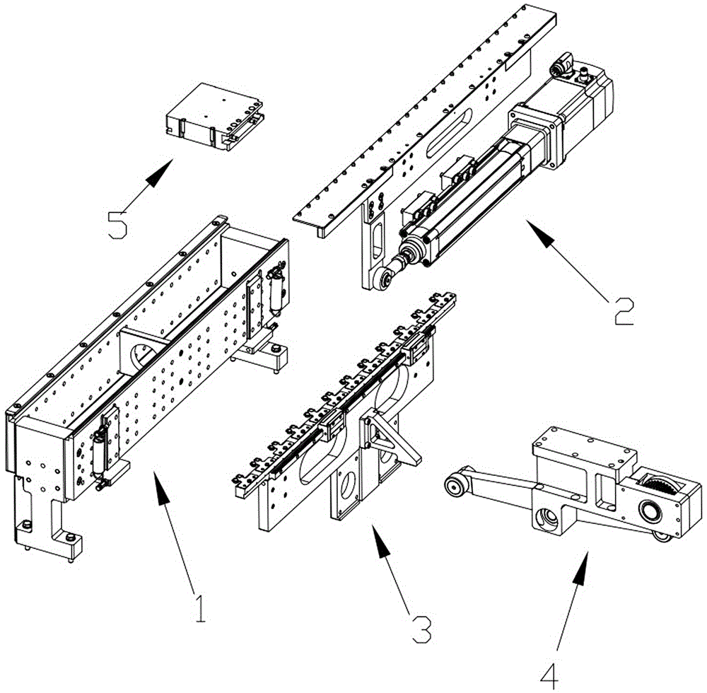
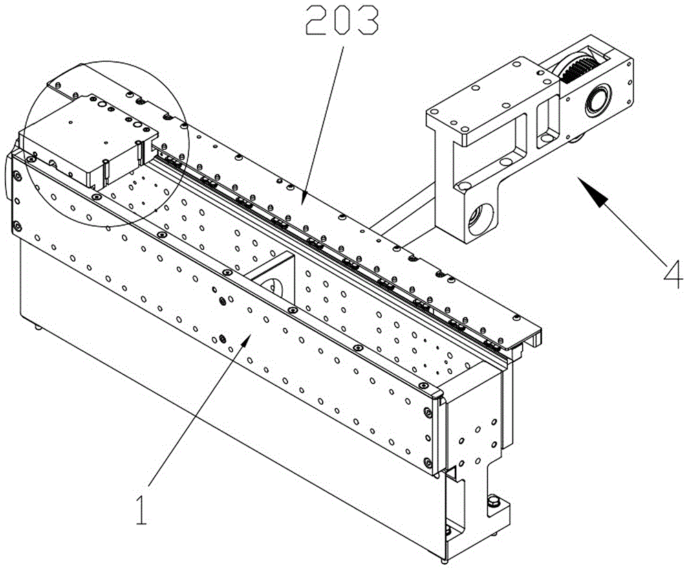
[0027] In this embodiment, refer to Figure 1 to Figure 7 , the specific implementation of the precise traction mechanism used to drive the tray includes a transmission base 1, a cam drive assembly 4, a lifting assembly 3 and a traction assembly 2, the top of the transmission base 1 is provided with a horizontal slide rail, and on the horizontal slide rail there is a The tray 5 that can slide horizontally along the horizontal slide rail.

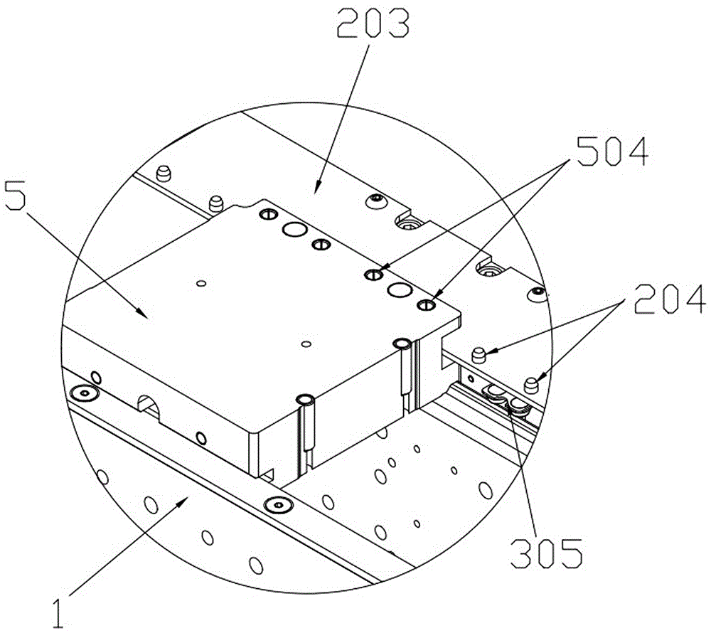
[0028] Such as Figure 7 As shown, the left side of the tray 5 is provided with a first horizontal chute 501, and the right side of the tray 5 is provided with a second horizontal chute 502. In the smooth rail, a clamping positioning column 503 is provided on the inner bottom surface of the second horizontal chute 502, and a grasping positioning column 504 is arranged above the clamping positionin...


PUM


Abstract

The invention relates to the field of mechanical transmission, in particular to an accurate traction mechanism for driving a tray. The accurate traction mechanism for driving the tray comprises a conveying base, a cam transmission assembly, a lifting assembly and a traction assembly. A horizontal sliding rail is installed at the top of the conveying base, and the tray which can horizontally slide along the horizontal sliding rail is installed on the horizontal sliding rail; a first horizontal sliding groove is formed in the left side of the tray, a second sliding groove is formed in the right side of the tray, and a clamping positioning pillar is installed on the inner bottom face of the second horizontal sliding groove; and a grabbing positioning pillar is installed above the clamping positioning pillar. The lifting assembly comprises a lifting main plate, a horizontal guide rail and a plurality of positioning plates. The traction assembly comprises an electric pushing rod, a traction main plate and a traction pin plate. The traction assembly is used for driving the tray to move horizontally, the lifting assembly is used for pressing the tray tightly so as to accurately position the tray, the traction assembly and the lifting assembly are both driven by the cam transmission assembly, and the driving mode is easy; any electronic control unit does not need to be adopted, any complex circuit does not need to be connected, and manufacturing cost is low.

Description

technical field [0001] The invention relates to the field of mechanical transmission equipment, in particular to a precise traction mechanism for driving a tray. Background technique [0002] In automated processing or assembly equipment, in order to meet the needs of mass production, most automated equipment can realize assembly line operations. In automated assembly line operation equipment, it is necessary to set the moving position of each station, and each station corresponds to Trays are provided, and the pallets are used to support workpieces, and each pallet can correspond to a work station. During the assembly line operation, the pallet is driven by the transmission mechanism, and the transmission mechanism moves the pallet from the first station to the last station, thus completing the automatic assembly. [0003] The conveying mechanism is used for conveying pallets, and can also be used for pressing pallets. There are two kinds of conveying mechanisms in the pri...

Claims


Application Information

Patent Timeline
Patent Type & Authority Applications(China)
IPC IPC(8): B23P19/00
CPCB23P19/008
Inventor 胡炎良
Owner HUNAN SUPER INFORMATION
Learn More