Supporting device used for tunnel primary supporting structure and construction method thereof
A support device and initial support technology, which is applied in mine roof support, earth square drilling, mining equipment, etc., can solve the problems of small welding operation space, increased welding difficulty, and difficult to guarantee welding effect, so as to reduce the operation difficulty and manufacture The process is simple and easy, and the effect of using a large space to create space
- Summary
- Abstract
- Description
- Claims
- Application Information
AI Technical Summary
Problems solved by technology
Method used
Image
Examples
Embodiment 1
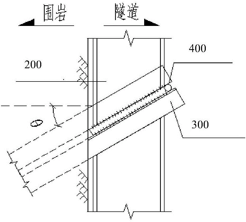
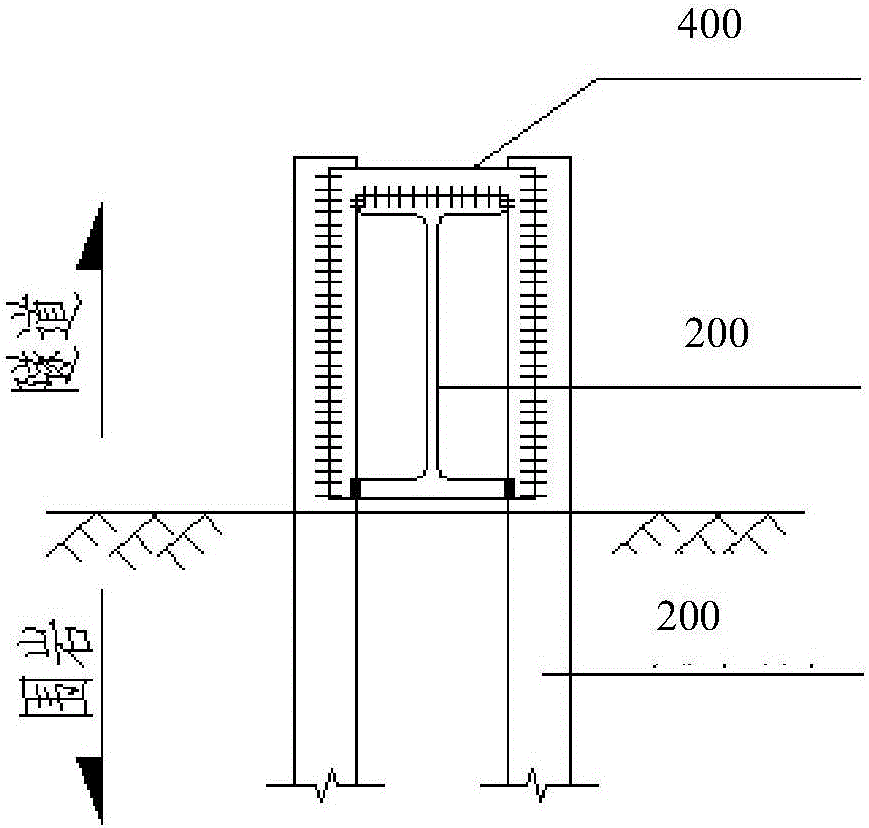
[0047] Such as Figure 1-3 As shown, the present invention shows a support device for the primary support structure of the tunnel, which includes a steel frame 1 and at least one anchor pipe with locking feet. Preferably, there are anchor pipes 2 and anchor pipes with locking feet in this embodiment. 2', 2 in total, and the specifications of the 2 locking foot anchor pipes 2 and 2' are the same, the steel frame 1 includes the first side 3 close to the tunnel surrounding rock and away from the tunnel surrounding rock, and with the The second side 4 opposite to the first side 3, in addition, also includes a connecting plate 5, and the connecting plate 5 includes a front side 7, a rear side 6 opposite to the front side 7, an upper side 8, and the upper side 8 and the upper side 8. The opposite lower side 9, and the rear side 6 is attached to the second side 4 of the steel frame 1; in this embodiment, the locking feet are provided symmetrically along the central axis X of the conne...
Embodiment 2
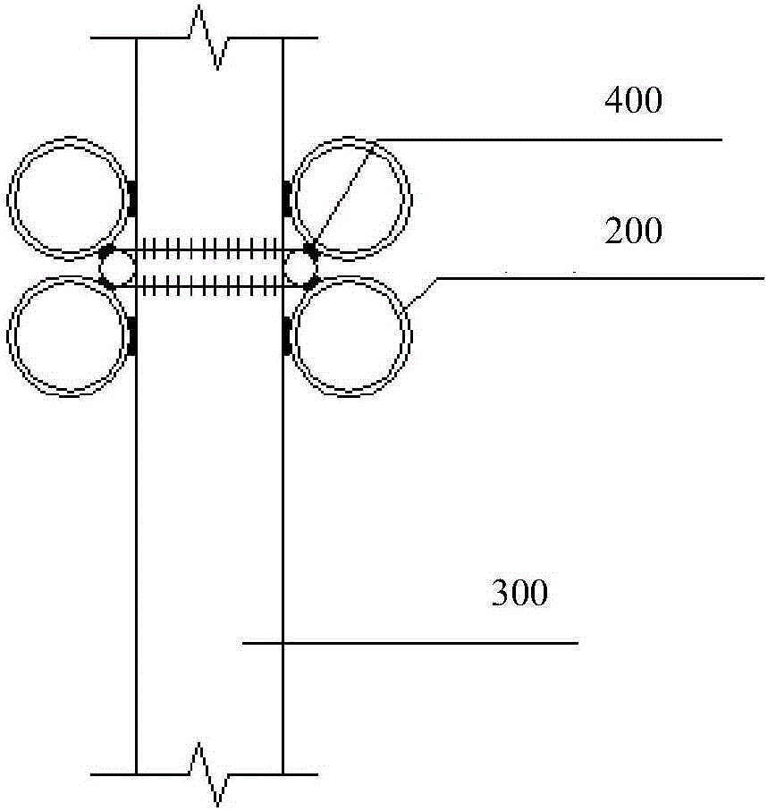
[0053] Such as Figure 5-7 As shown, the difference between the second embodiment and the first embodiment is that there are two anchor pipes 2 and 2' respectively, and there are four in total. When there are four locking foot anchor pipes, and the locking foot anchor pipes 2 and 2' are arranged symmetrically along the extension direction of the central axis X, the length L' of the connecting plate is (2d+1.5mm)×2 +b, the width W' is (3.5d+3.0mm)×2+b, and the thickness is 3-7mm; wherein, the b is the width of the I-beam flange plate; preferably, the thickness can be 7mm. Other features are the same as those in Embodiment 1, and will not be repeated here.
Embodiment 3
[0055] Figure 8 Shown is a kind of implementation method of above-mentioned support device, it is characterized in that, comprises the following steps:
[0056] S1. Prefabrication of the locking foot anchor pipe, section steel frame and connection plate; the size of the connection plate is determined according to the size of the section steel frame and the size and quantity of the locking foot anchor pipe;
[0057] S2. Fix the shaped steel frame and open the through hole on the connecting plate; or fix the shaped steel frame, open the through hole on the connecting plate, and open the through hole on the surrounding rock of the tunnel (such as drilling with a drilling rig) for fixing the fixing hole of the anchor pipe of the locking foot, and cleaning the fixing hole;
[0058] S3. Attach the connecting plate provided with the through hole to the second side of the steel frame, and align the upper side and / or lower side of the connecting plate with the second side of the stee...
PUM
 Abstract
Description
Claims
Application Information
 - R&D
- Intellectual Property
- Life Sciences
- Materials
- Tech Scout
- Unparalleled Data Quality
- Higher Quality Content
- 60% Fewer Hallucinations
Browse by: Latest US Patents, China's latest patents, Technical Efficacy Thesaurus, Application Domain, Technology Topic, Popular Technical Reports.
© 2025 PatSnap. All rights reserved.Legal|Privacy policy|Modern Slavery Act Transparency Statement|Sitemap|About US| Contact US: help@patsnap.com


