
Two-way spiral vacuum tube structure capable of being used for air type solar heat collector

A technology of solar collectors and vacuum tubes, applied in solar thermal power generation, solar thermal devices, heating devices, etc., can solve the problems of system service life decline, antifreeze leakage, paralysis, etc., to reduce the possibility of broken tubes and ensure Stability and safety, likelihood reduction effects

Inactive Publication Date: 2017-05-24
SHANGHAI ZN ENERGY ENVIRONMENTAL TECH
View PDF0 Cites 0 Cited by
  • Summary
  • Abstract
  • Description
  • Claims
  • Application Information

AI Technical Summary

Problems solved by technology

[0002] The traditional solar thermal system that uses water as the heat transfer medium cannot be used in the western and northern alpine regions of my country because of the low freezing point of water.
[0003] In order to widely promote solar energy products in alpine regions, the current common practice in the industry is to use antifreeze as the heat transfer medium to lower the freezing point of the heat transfer medium in the solar system, but the solar system using antifreeze as the heat transfer medium is due to the Too much, thermal expansion and contraction in the day and night cycle will generally cause the problem of antifreeze leakage in the system, resulting in reduced service life of the system and high maintenance costs

Method used


Image

  • Two-way spiral vacuum tube structure capable of being used for air type solar heat collector

Examples


Embodiment Construction

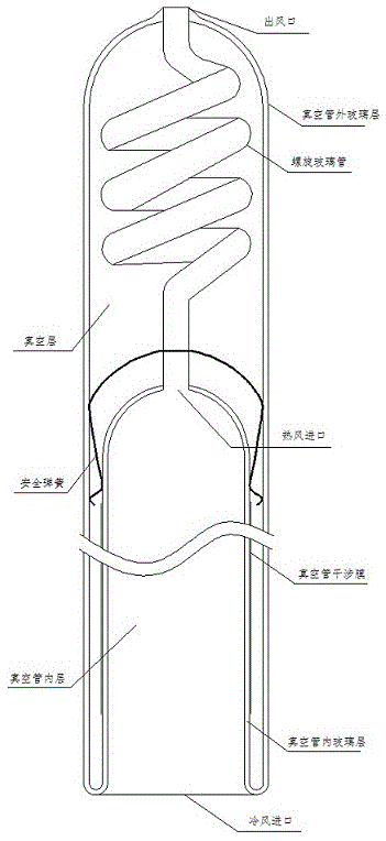
[0017] like figure 1 As shown, the present invention provides a double-pass spiral vacuum tube structure that can be used in air-type solar collectors. The double-pass spiral vacuum tube structure includes: vacuum tube outer glass layer, vacuum tube inner glass layer, spiral glass tube, vacuum tube interference film, safety Spring, vacuum layer, inner layer of vacuum tube, cold air inlet, hot air inlet and air outlet, wherein the outer glass layer of the vacuum tube is connected with the inner glass layer of the vacuum tube, the joint is the cold air inlet, one end of the spiral glass tube is connected with the inner glass layer of the vacuum tube, and the joint is It is the hot air inlet. The other end of the spiral glass tube is connected to the outer glass layer of the vacuum tube. The connection is the air outlet. The area wrapped by the inner glass layer of the vacuum tube between the cold air inlet and the hot air inlet is the inner layer of the vacuum tube. The vacuum l...


PUM


Abstract

The invention provides a two-way spiral vacuum tube structure capable of being used for an air type solar heat collector. The two-way spiral vacuum tube structure comprises a vacuum tube outer glass layer, a vacuum tube inner glass layer, a spiral glass tube, a vacuum tube interference film, a safety spring, a vacuum layer, a vacuum tube inner layer, a cold air inlet, a hot air inlet and an air outlet, wherein the vacuum tube outer glass layer is connected with the vacuum tube inner glass layer, and the cold air inlet is formed in the joint of the vacuum tube outer glass layer and the vacuum tube inner glass layer; one end of the spiral glass tube is connected with the vacuum tube inner glass layer, and the hot air inlet is formed in the joint of the spiral glass tube and the vacuum tube inner glass layer; the other end of the spiral glass tube is connected with the vacuum tube outer glass layer, and the air outlet is formed in the joint of the spiral glass tube and the vacuum tube outer glass layer; an area, packaged by the vacuum tube inner glass layer, between the cold air inlet and the hot air inlet is the vacuum tube inner layer; a vacuum layer is defined by the vacuum tube outer glass layer, the vacuum tube inner glass layer and the spiral glass tube; the vacuum tube interference film is arranged on an surface on which the vacuum tube inner glass layer is in contact with the vacuum layer; and the safety spring is fixedly arranged in the vacuum layer, and is packaged at a joint of the vacuum tube inner glass layer and the spiral glass tube, and a small hole penetrates through the joint from the spiral glass tube.

Description

technical field [0001] The invention relates to the technical field of air-type solar heat storage, in particular to a double-pass spiral vacuum tube structure that can be used in an air-type solar heat collector. Background technique [0002] The traditional solar thermal system that uses water as the heat transfer medium cannot be used in the western and northern alpine regions of our country because of the low freezing point of water. [0003] In order to widely promote solar energy products in alpine regions, the current common practice in the industry is to use antifreeze as the heat transfer medium to lower the freezing point of the heat transfer medium in the solar system, but the solar system using antifreeze as the heat transfer medium is due to the Too much, thermal expansion and contraction in the day and night cycle will generally cause the problem of antifreeze leakage in the system, resulting in reduced service life of the system and high maintenance costs. ...

Claims


Application Information

Patent Timeline
Patent Type & Authority Applications(China)
IPC IPC(8): F24J2/46
CPCY02E10/40
Inventor 苏树强石红波苏啸
Owner SHANGHAI ZN ENERGY ENVIRONMENTAL TECH
Learn More