
Refrigerant piping device

A refrigerant and return pipe technology, applied in refrigerators, refrigeration components, refrigeration and liquefaction, etc., can solve the problems of embrittlement of the refrigerant return pipe 15, the inability of the user to continue working, and the exhaustion of the refrigerant.

Inactive Publication Date: 2017-05-24
谢德音 +1
View PDF14 Cites 2 Cited by
  • Summary
  • Abstract
  • Description
  • Claims
  • Application Information

AI Technical Summary

Problems solved by technology

[0004] Because the temperature of the refrigerant passing through the refrigerant return pipe 15 is extremely low, it will cause the refrigerant return pipe 15 to freeze and become brittle. In addition, the high-speed reciprocating action will produce a pulling effect, which will make the refrigerant return pipe 15 continuously tightened, and finally Cause metal fatigue damage and make it break and break, causing the refrigerant to leak from the cracks, and the user will not be able to continue working and suffer losses

Method used


Image

  • Refrigerant piping device
  • Refrigerant piping device
  • Refrigerant piping device

Examples


Embodiment Construction

[0027] Before the present invention is described in detail, it should be noted that in the following description, similar components are denoted by the same numerals.

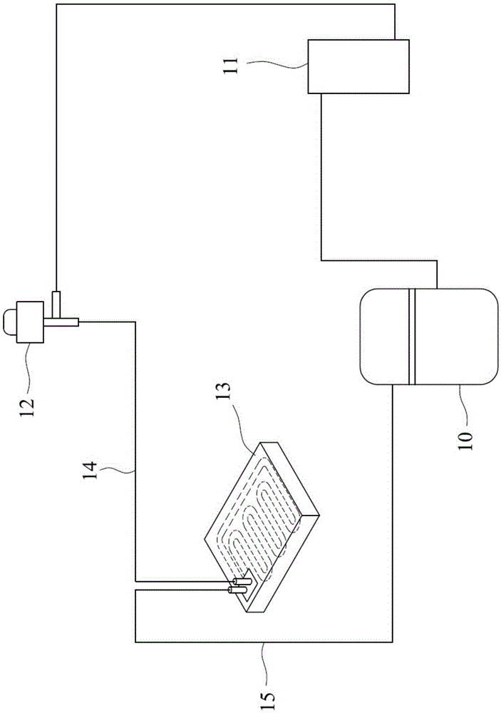
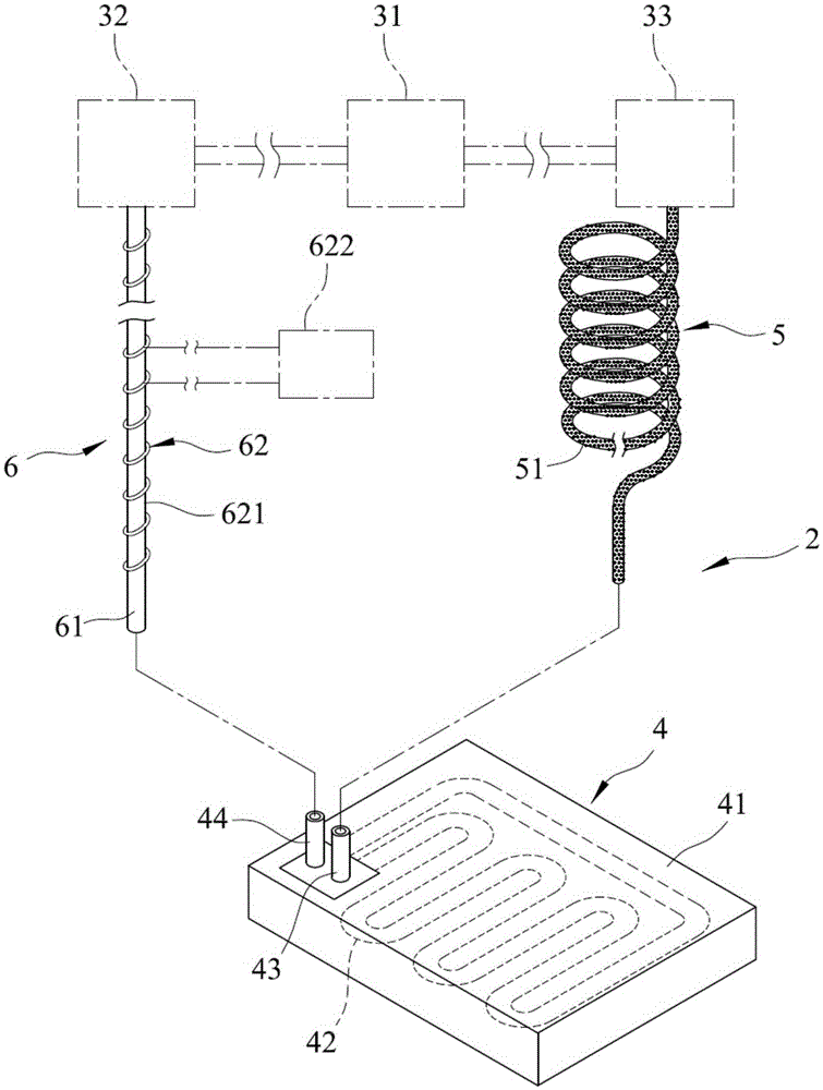
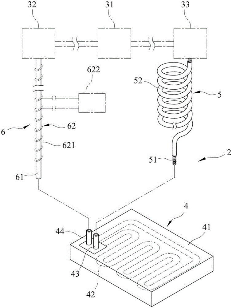
[0028] refer to figure 2 , is the first embodiment of the refrigerant piping device 2 of the present invention, the refrigerant piping device 2 is used in conjunction with a condenser 31, a compressor 32, and a refrigerant controller 33, the condenser 31, the compressor 32, and the refrigerant controller 33 is like figure 2 As shown, they communicate with each other. In the first embodiment, the refrigerant controller 33 is preferably a solenoid valve with a capillary tube. The refrigerant piping device 2 includes a refrigerant head 4 , an input unit 5 connected to the refrigerant controller 33 and the refrigerant head 4 to input refrigerant, and an output unit 6 connected to the refrigerant controller 33 and the compressor 32 to output refrigerant.

[0029] The freezing head 4 includes a main body 41, a he...


PUM


Abstract

The invention discloses a refrigerant piping device being a device located in a low-temperature freezing state and capable of performing a high-speed reciprocating motion. The refrigerant piping device comprises a freezing head, an input unit communicated with the freezing head for inputting a refrigerant, and an output unit communicated with the freezing head for outputting the refrigerant. The output unit includes a refrigerant reflux pipe communicated with the freezing head, and a heating module arranged on the refrigerant reflux pipe for heating the refrigerant in the refrigerant reflux pipe. The refrigerant reflux pipe is provided with a heating module for heating the refrigerant in the heating pipe; and the freezing state of the refrigerant reflux pipe can be eliminated by dint of the heating effect to recover flexible functions and effects of the refrigerant reflux pipe, so that the freezing embrittlement state of the refrigerant reflux pipe due to low temperature can be prevented, and the breakage of the freezing head due to left-right, front-back or up-down high-speed reciprocating actions can be prevented.

Description

technical field [0001] The invention relates to a refrigerant piping device, in particular to a refrigerant piping device used in conjunction with a condenser and a compressor. Background technique [0002] refer to figure 1 , the general refrigerant cycle system relies on the compressor 10 to compress the low-temperature and low-pressure refrigerant into a high-temperature and high-pressure gaseous refrigerant, and then the condenser 11 cools and dissipates heat, and the gaseous refrigerant condenses into a liquid refrigerant at room temperature and high pressure, and is cooled by the refrigerant controller 12. After compression, the liquid refrigerant will enter the evaporator 13 at a low temperature to evaporate and absorb heat, and then become a low-temperature and low-pressure gaseous refrigerant, and return to the compressor 10 to repeat the same cycle, and the compressor 10 will run continuously for a long time The resulting refrigeration effect can achieve the effec...

Claims


Application Information

Patent Timeline
IPC IPC(8): F25B41/00F25B47/00F25B41/40
CPCF25B41/00F25B47/006
Inventor 谢德音谢德风
Owner 谢德音
Learn More