Coding disc, photoelectric angle measurement encoder using same, and work method thereof
An encoder disk and encoder technology, which is applied in the use of optical devices to transmit the directions of sensing components, instruments, measuring devices, etc., can solve problems such as high angle measurement accuracy, and achieve improved measurement speed, accuracy and recognition speed. The effect of sex and precision
- Summary
- Abstract
- Description
- Claims
- Application Information
AI Technical Summary
Problems solved by technology
Method used
Image

Examples
Embodiment 1
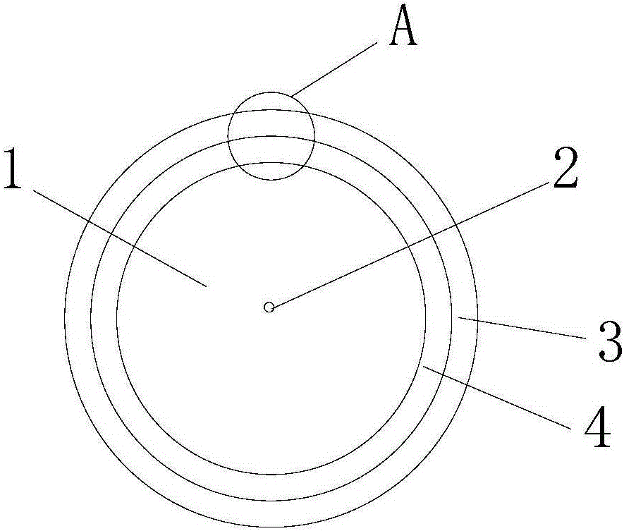
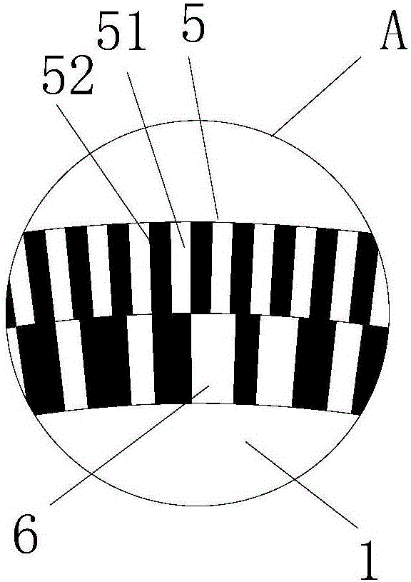
[0026] The coding disk of the present embodiment includes a barcode grating disk 1, such as figure 1 As shown, the barcode grating disk is a double code track disk (the light-transmitting code and the opaque code in the code track are not shown), the first code track 3 is set adjacent to the peripheral edge of the grating disk 1, and the second code track 4 is adjacent to The inner side of the first lane 3 is set; such as figure 2 As shown, in the first code track 3 is a one-dimensional incremental relative code 5 of 2500 lines, which is composed of 2500 light-transmitting codes 51 and opaque codes 52 arranged alternately at equal intervals; in the second code track 4 is 1080 lines The single-turn one-dimensional absolute coding 6 of the line, the center 2 of the barcode grating disk 1 is fixedly assembled with the rotating shaft, ensuring that the rotating center of the rotating shaft is concentric with the rotating center of the code track of the grating disk.
Embodiment 2
[0028] The code disc of the present embodiment also includes a barcode grating disc 1, which is a double code track disc above the bar code grating disc 1, the second code track 4 is arranged adjacent to the peripheral edge of the grating disc 1, and the first code track 3 is next to the second code track 4 is set on the inner side; the first code track 3 is a one-dimensional incremental relative code 5 of 2500 lines, which is composed of 2500 light-transmitting codes 51 and opaque codes 52 arranged alternately at equal intervals; the second code track 4 is 1080 lines of single-turn one-dimensional absolute encoding 6, the center 2 of the barcode grating disk 1 is fixedly assembled with the rotating shaft, ensuring that the rotating center of the rotating shaft is concentric with the rotating center of the code track of the grating disk.
Embodiment 3
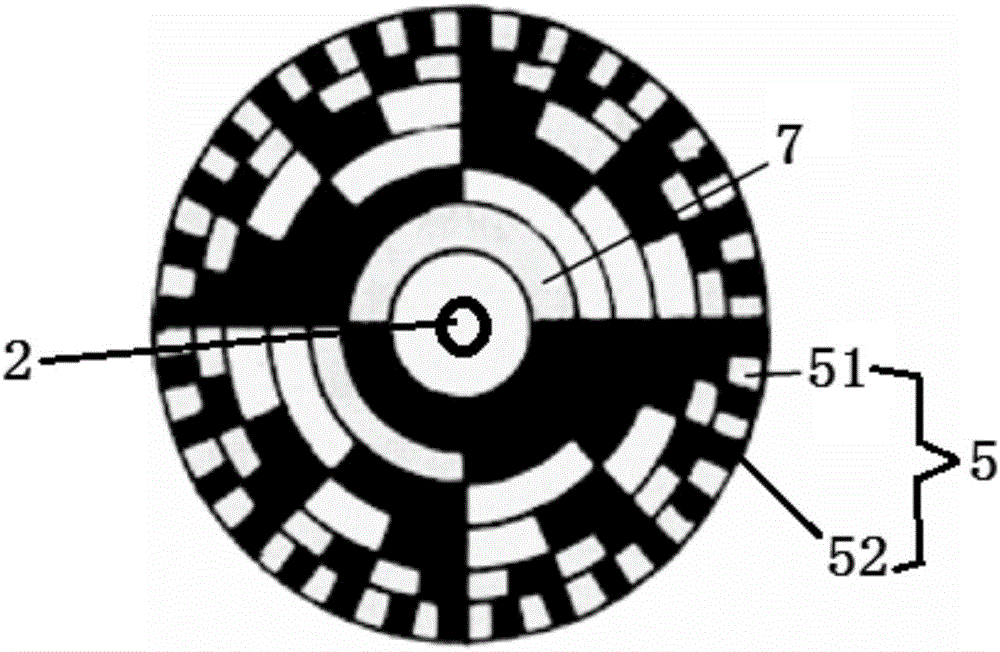
[0030] Such as image 3 As shown, the code disk of this embodiment includes a barcode grating disk 1 provided with a one-dimensional incremental relative code 5 and a two-dimensional absolute code 7. Incremental relative codes 5 are composed of light-transmitting codes 51 and opaque codes 52 arranged alternately at equal intervals; two-dimensional absolute codes 7 are arranged inside one-dimensional incremental relative codes 5, and one-dimensional incremental relative codes 5 and two-dimensional Dimensional absolute encoding of 7 concentric settings.
PUM
 Abstract
Description
Claims
Application Information
 - Generate Ideas
- Intellectual Property
- Life Sciences
- Materials
- Tech Scout
- Unparalleled Data Quality
- Higher Quality Content
- 60% Fewer Hallucinations
Browse by: Latest US Patents, China's latest patents, Technical Efficacy Thesaurus, Application Domain, Technology Topic, Popular Technical Reports.
© 2025 PatSnap. All rights reserved.Legal|Privacy policy|Modern Slavery Act Transparency Statement|Sitemap|About US| Contact US: help@patsnap.com