Optical transmission window for atomic clock

A technology of optical transmission and atomic clocks, applied in the field of atomic clocks, can solve the problems of batch coating of optical lenses, etc., and achieve the effects of increasing yield, reducing damage probability, and improving coating efficiency

Active Publication Date: 2017-05-24
NO 12 RES INST OF CETC
View PDF37 Cites 0 Cited by
  • Summary
  • Abstract
  • Description
  • Claims
  • Application Information

AI Technical Summary

Problems solved by technology

Through the improvement of the structure of the optical transmission window, the present invention is suitable for the batch coating needs of the optical transmission window, and solves the problem that the traditional optical transmission window cannot be coated with multiple optical transmission windows at the same time by the existing coating machine due to the limitation of its structure. The problem of batch coating of optical lenses in

Method used


Image

  • Optical transmission window for atomic clock
  • Optical transmission window for atomic clock
  • Optical transmission window for atomic clock

Examples


Embodiment 1

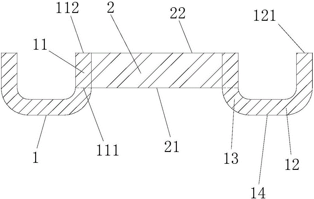
[0036] Such as figure 1 , 2 As shown, an optical transmission window for an atomic clock, the optical transmission window includes a sleeve 1 and an optical lens 2 arranged in the sleeve 1; the cylinder wall of the sleeve 1 includes a vertical side wall portion 11, and an extension part 12 located at the bottom end of the vertical side wall part 11 and extending outward along the circumferential direction of the bottom end of the vertical side wall part 11; the extension part 12 is Shaped structure; preferably, an arc-shaped transition portion 13 is provided between the vertical side wall portion 11 and the extension portion 12 . The end 121 of the extension part 12 is the connection end where the optical transmission window is connected and fixed to the metal casing of the vacuum atomic device. Preferably, the cylinder wall of the sleeve 1 is of an integral structure.

[0037] The circumferential side wall surface of the optical lens 2 is sealed and fixed to the inner wal...

Embodiment 2

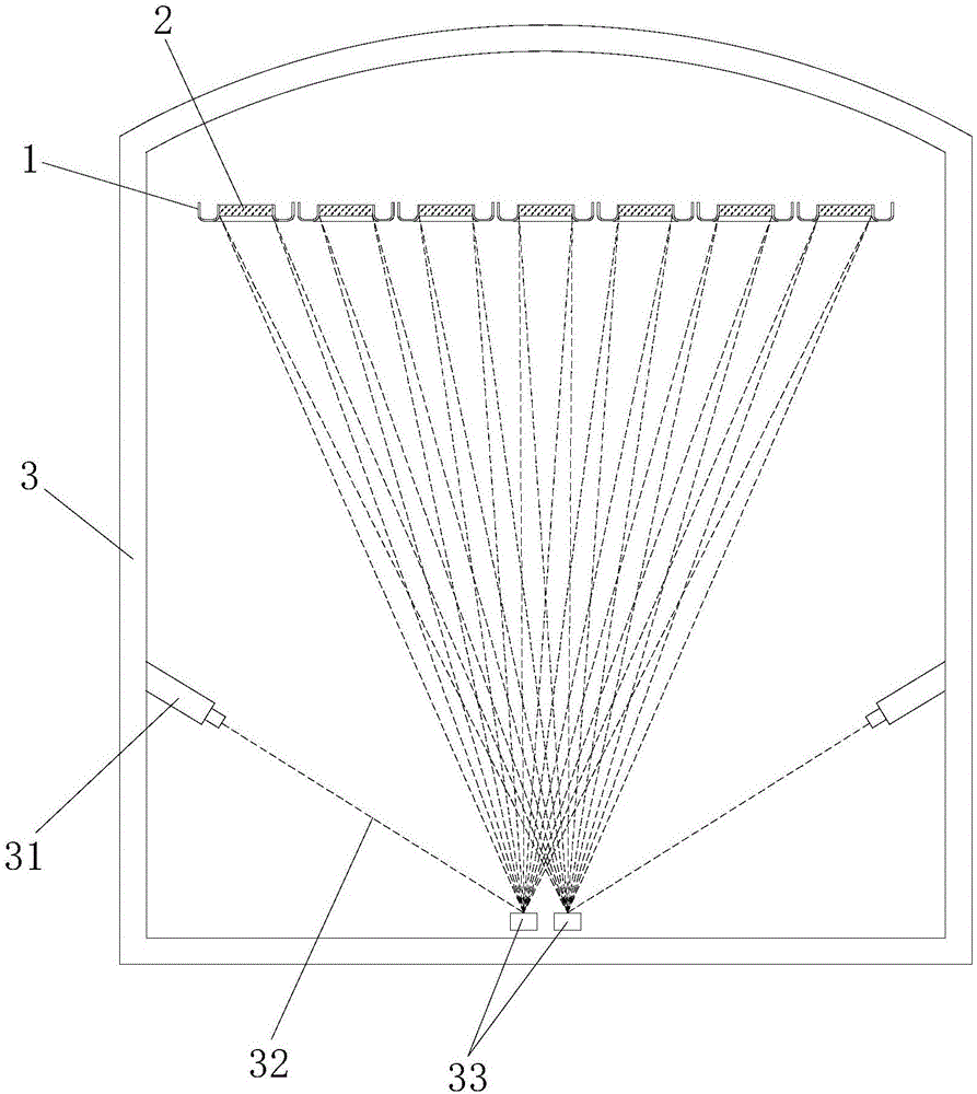
[0042] Such as image 3 As shown, an optical transmission window for an atomic clock, the optical transmission window includes a sleeve 1 and an optical lens 2 arranged in the sleeve 1; the cylinder wall of the sleeve 1 includes a vertical side wall portion 11, and an extension portion 12 located at the bottom end of the vertical side wall portion 11 and extending outward along the circumference of the bottom end of the vertical side wall portion 11; the extension portion 12 has a straight structure; preferably, An arc-shaped transition portion 13 is provided between the vertical side wall portion 11 and the extension portion 12 . The end 121 of the extension part 12 is the connection end where the optical transmission window is connected and fixed to the metal casing of the vacuum atomic device. Preferably, the cylinder wall of the sleeve 1 is of an integral structure.

[0043] The circumferential side wall surface of the optical lens 2 is sealed and fixed to the inner wall...

Embodiment 3

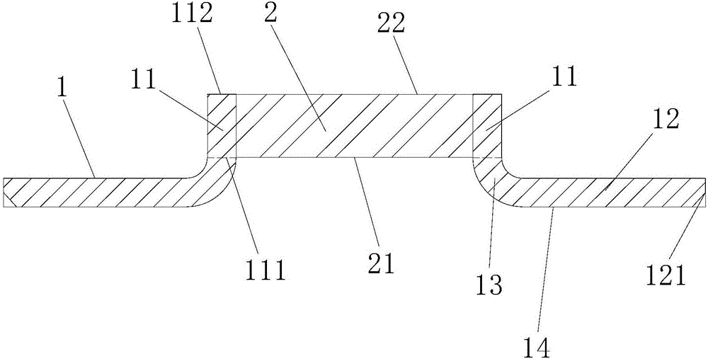
[0046] Such as Figure 4 As shown, an optical transmission window for an atomic clock, the optical transmission window includes a sleeve 1 and an optical lens 2 arranged in the sleeve 1; the cylinder wall of the sleeve 1 includes a vertical side wall portion 11, and an extension portion 12 located at the bottom end of the vertical side wall portion 11 and extending outward along the circumference of the bottom end of the vertical side wall portion 11; the extension portion 12 has a “”-shaped structure; preferably, An arc-shaped transition portion 13 is provided between the vertical side wall portion 11 and the extension portion 12 . The end 121 of the extension part 12 is the connection end where the optical transmission window is connected and fixed to the metal casing of the vacuum atomic device. Preferably, the cylinder wall of the sleeve 1 is of an integral structure.

[0047] The circumferential side wall surface of the optical lens 2 is sealed and fixed to the inner si...


PUM


Abstract

The invention discloses an optical transmission window for an atomic clock; the optical transmission window comprises sleeves and optical lenses arranged in the sleeves; a body wall of each sleeve comprises a vertical sidewall portion and an extension portion positioned at the bottom end of the vertical sidewall portion and peripherally extended out from the bottom end of the vertical sidewall portion; the peripheral sidewall of each optical lens is hermetically fixed to the inner wall surfaces of the vertical sidewall portions of the corresponding body walls; the bottom of each optical lens is flush with the bottom edges of the vertical sidewall portions of the body walls. By modifying the structure of the optical transmission window, the need for batch coating of optical transmission windows is met, and the problem is solved that optical lenses in the multiple traditional optical transmission windows cannot be coated in batch at a time through an existing coating machine due to their structure limits.

Description

technical field [0001] The invention relates to the technical field of atomic clocks. More specifically, it relates to an optically transmissive window for an atomic clock. Background technique [0002] An atomic clock is an instrument that uses atomic energy level transitions to achieve high-precision time and frequency output. It is widely used in communication, navigation, timekeeping and other fields. Vacuum atomic devices are its physical core. In order to maintain ultra-high vacuum, the shell of vacuum atomic devices is generally welded with metal. When preparing atomic energy levels and exciting atoms to make transitions, it is necessary to transmit laser beams of a certain frequency into the interior of vacuum atomic devices to interact with atoms. In order to miniaturize and meet engineering applications, optical devices sealed by metallization are generally used. The transmission window is to coat the metallized layer on the side of the optical lens, and then use...

Claims


Application Information

Patent Timeline
Patent Type & Authority Applications(China)
IPC IPC(8): G04F5/14G02B7/00
CPCG02B7/007G04F5/14
Inventor 陈海军郑玥杨剑青刘忠征梁友焕李莉莉肖顺禄
Owner NO 12 RES INST OF CETC
Why Eureka
Try Eureka