A method for improving the quality of the lower surface of ultra-thin glass
A technology of surface quality and ultra-thin glass, which is applied in the direction of program control, program control, and instrumentation in sequence/logic controllers, to achieve the effects of easy implementation, reduction of scratches, and avoidance of sliding friction
- Summary
- Abstract
- Description
- Claims
- Application Information
AI Technical Summary
Problems solved by technology
Method used
Image
Examples
Embodiment 1
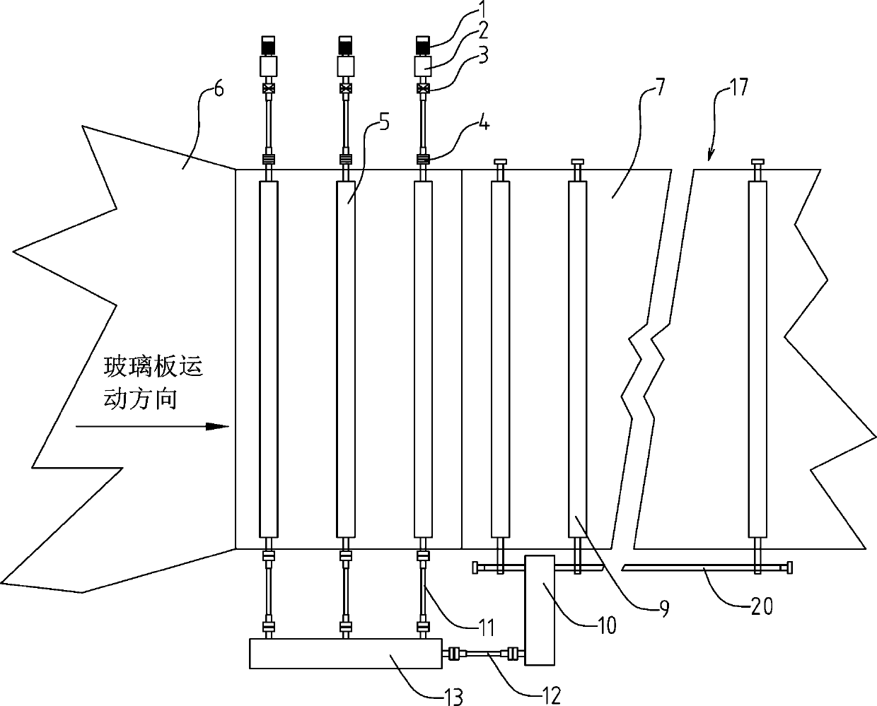
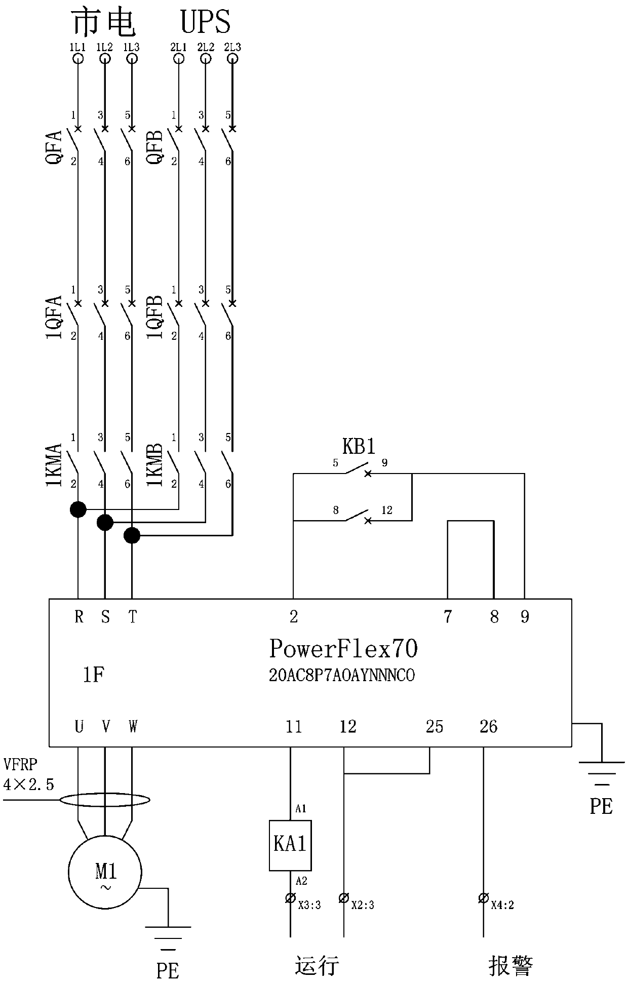
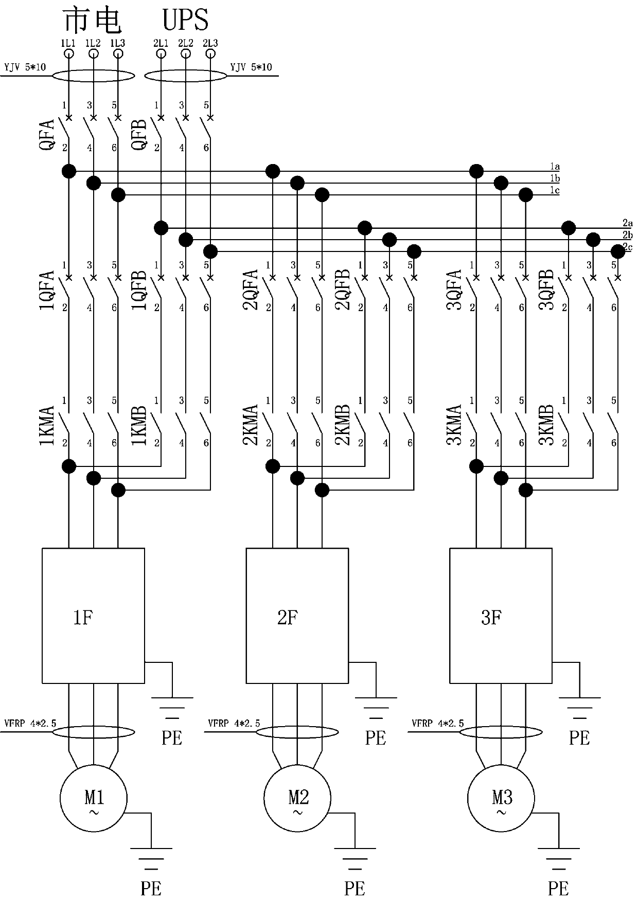
[0040] Such as Figure 1~6 Among them, a method for improving the quality of the lower surface of ultra-thin glass includes a plurality of transition rollers 5 located between the tin bath 6 and the annealing furnace 17, and one end of the plurality of transition rollers 5 is respectively connected with a slave transmission device, and the slave transmission device Drive the transition roller 5 to rotate, and the slave transmission device is equipped with a speed sensor and a torque sensor. Under the working condition of conveying the glass plate 7, according to the feedback of the torque sensor, the PLC adjusts the speed of each slave transmission device, so that the transmission to each transition roller 5 The torque remains consistent.
[0041] The preferred solution is as figure 1 In the above-mentioned slave transmission device, one end of the first coupling 3 is connected to the transition roller 5, the other end of the first coupling 3 is fixedly connected to the reducer...
Embodiment 2
[0053] On the basis of Embodiment 1, under the working condition of conveying the glass plate 7, the PLC controls the main transmission device to output torque at the initial speed, and the PLC controls the slave transmission device to output torque at a delivery speed slightly higher than the initial speed; when the slave transmission device The output speed is gradually higher than the output speed of the main transmission, the overrunning clutch 13 of the main transmission is disengaged, and the transition roller 5 is mainly driven to rotate by the slave transmission.
[0054] In this state, choose any torque value from the torque sensor 8 in the transmission as the working torque value;
[0055] Compare other torque values detected by the torque sensor 8 in the transmission with the operating torque value, and when higher than the operating torque value, the PLC controls the slave transmission to reduce the speed;
[0056] When it is lower than the working torque value, ...
Embodiment 3
[0058] On the basis of Example 1, in the preferred scheme, such as Figure 7 As shown in , a working torque value is set in the PLC according to the working conditions, and the torque value detected by each torque sensor 8 of the transmission device is compared with the working torque value. When the working torque value is higher than the working torque value, the PLC controls Reduce the speed from the transmission;
[0059] When it is lower than the working torque value, the PLC controls the slave transmission to increase the speed; through the above steps, the torque of the slave transmission is kept consistent. The advantage of this scheme is that it is easy to control and has high reliability.
PUM
 Abstract
Description
Claims
Application Information
 - R&D
- Intellectual Property
- Life Sciences
- Materials
- Tech Scout
- Unparalleled Data Quality
- Higher Quality Content
- 60% Fewer Hallucinations
Browse by: Latest US Patents, China's latest patents, Technical Efficacy Thesaurus, Application Domain, Technology Topic, Popular Technical Reports.
© 2025 PatSnap. All rights reserved.Legal|Privacy policy|Modern Slavery Act Transparency Statement|Sitemap|About US| Contact US: help@patsnap.com


