
Commutation torque ripple suppression device and suppression method for brushless DC motor

A technology for brush DC motor and pulsation suppression, which is applied in the field of device for suppressing brushless DC motor commutation torque pulsation and brushless DC motor control device, can solve the problems of errors in the manufacturing process, influence of DC brushless motor, non-commutation Phase current fluctuations and other issues, to achieve the effect of low cost, easy transformation and upgrading, and fewer components

Active Publication Date: 2017-05-24
HARBIN ENG UNIV
View PDF7 Cites 11 Cited by
  • Summary
  • Abstract
  • Description
  • Claims
  • Application Information

AI Technical Summary

Problems solved by technology

[0004] 1. There are errors in the manufacturing process, which will lead to periodic torque ripple
[0005] 2. The PWM modulation method will cause small-amplitude high-frequency torque ripple
[0006] 3. Commutation torque pulsation, which accounts for about 50% of the total pulsation, is the most serious factor affecting the brushless DC motor
If the drop rate of the off-phase current is not equal to the rise rate of the on-phase current, it will cause fluctuations in the non-commutation current, resulting in commutation torque ripple

Method used


Image

  • Commutation torque ripple suppression device and suppression method for brushless DC motor
  • Commutation torque ripple suppression device and suppression method for brushless DC motor
  • Commutation torque ripple suppression device and suppression method for brushless DC motor

Examples


Embodiment

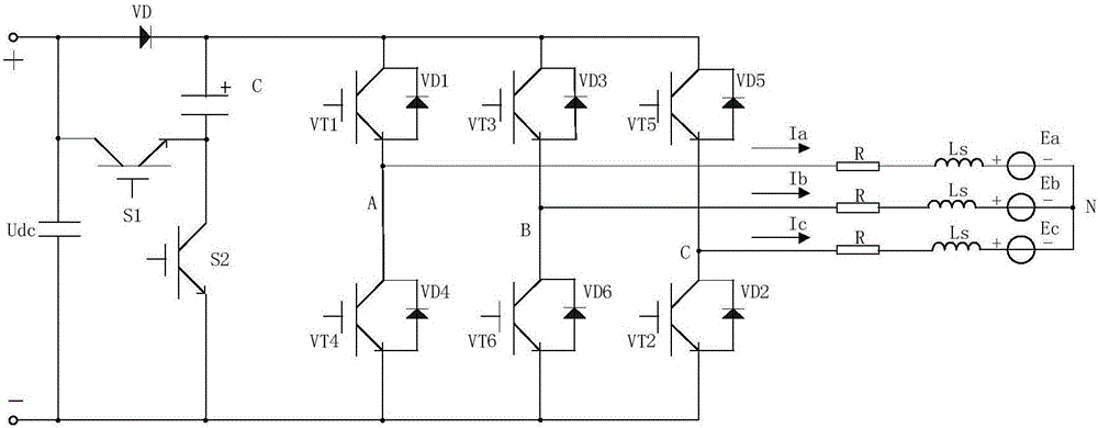
[0032] The parameters of the brushless DC motor used in the present invention are: rated power 3.7kW, rated voltage 300V, rated speed 1500rmp, inductance 0.188mH, back electromotive force coefficient 0.592. In this example, the voltage across the capacitor is charged to 90V.

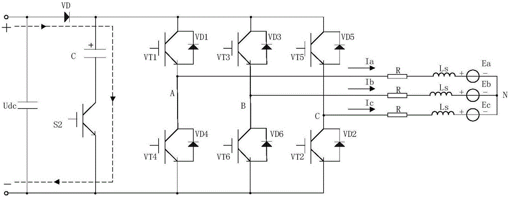
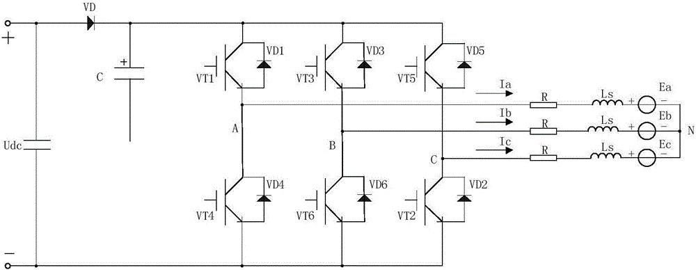
[0033] image 3 In (a), the DC bus voltage during the non-commutation period is the power supply voltage 300V, and the DC bus voltage during the commutation period is the sum of the power supply voltage and the capacitor voltage 390V. Figure 4 It is the three-phase current waveform diagram and the torque waveform diagram of the embodiment without using the method of the present invention. From Figure 4 It can be seen from the figure that during commutation, the rate of commutation current decrease and rate of increase are not equal, and the commutation torque ripple is relatively large. At this time, the torque is 22N*m, the minimum torque value is 17N*m during commutation, and the torque change rat...


PUM


Abstract

The present invention provides a commutation torque ripple suppression device and a suppression method for a brushless DC motor. The device comprises two power switches (S1 and S2), a power diode (VD) and a capacitor (C). The collector of the second power switch (S2) is connected in series with the cathode of the capacitor (C). The anode of the capacitor (C) is connected with the cathode of the power diode (VD). The emitter of the second power switch (S2) is connected with the negative electrode of a power supply. The collector of the first power switch (S1) and the anode of the power diode (VD) are connected with the positive electrode of the power supply. The emitter of the first power switch (S1) is connected with the cathode of the capacitor (C). According to the technical scheme of the invention, the advantages of fewer components, simple control method, low cost and easy implementation are realized. If the device breaks down, the normal operation of the motor is not influenced at all. Therefore, the fault tolerance rate is high. The device and a bus are connected in parallel, so that the transformation and the upgrading of existing equipment are facilitated.

Description

technical field [0001] The invention relates to a brushless DC motor control device, and the invention also relates to a brushless DC motor control method. Specifically, it is a device and method for suppressing commutation torque ripple of a brushless DC motor. Background technique [0002] Brushless DC motors have been widely used in various industrial fields due to their high power density, high torque, high power factor, simple control, and low maintenance cost. However, due to the torque ripple of the motor, its application in the high-precision field is limited. [0003] The main causes of torque ripple are as follows: [0004] 1. There are errors in the manufacturing process, which will lead to periodic torque ripple. [0005] 2. The PWM modulation method will cause small-amplitude high-frequency torque ripple. [0006] 3. Commutation torque pulsation, which accounts for about 50% of the total pulsation, is the most serious factor affecting the brushless DC motor....

Claims


Application Information

Patent Timeline
Patent Type & Authority Applications(China)
IPC IPC(8): H02P6/10
CPCH02P6/10
Inventor 姚绪梁赵继成江晓明杨光仪王峰林浩张永奇张燕常英健孙小琴
Owner HARBIN ENG UNIV
Learn More