
Low-complexity signal detection method for MIMO FBMC-OQAM (Multiple Input Multiple Output Filter Bank Multicarrier Offset-QAM) system
A system signal and detection method technology, applied in the transmission system, multi-carrier system, digital transmission system, etc., can solve the problems of MIMO technology combination constraints, achieve good detection performance, eliminate system internal interference, and improve computing efficiency.
Patent Information
- Authority / Receiving Office
- CN · China
- Current Assignee / Owner
- Publication Date
- 2017-05-24
Smart Images
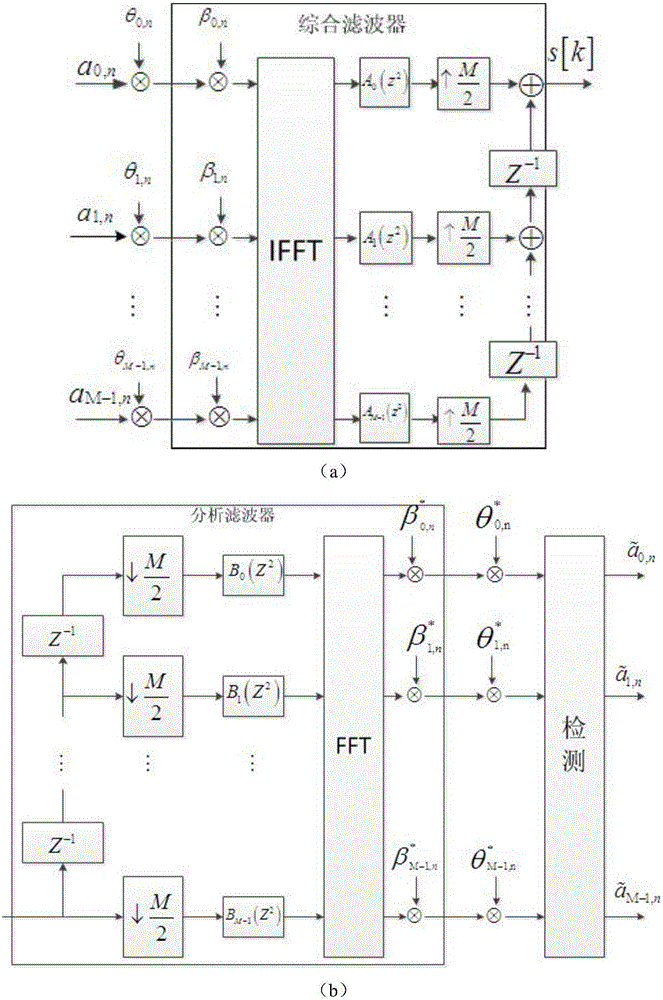
Figure 1 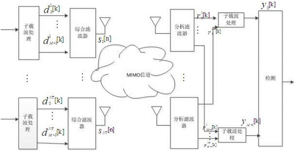
Figure 2 
Figure 3
Abstract
Description
technical field
[0001] The invention belongs to the technical field of wireless communication, in particular to the field of multiple input multiple output (Multiple Input Multiple Output, MIMO) filter bank multicarrier-offset quadrature amplitude modulation (Filter Bank Multicarrier Offset-QAM, FBMC-OQAM) system field, and relates to a A low-complexity MIMO FBMC-OQAM system signal detection method. Background technique
[0002] In the fourth-generation mobile communication, the advantages of multiple input multiple output (Multiple Input Multiple Output, MIMO) technology in improving system capacity and Orthogonal Frequency-division Multiplexing (OFDM) technology in combating multipath fading , The combination of the two has aroused deep concern in the industry for a period of time. However, in the fifth generation mobile communication system (5G), the application of OFDM in 5G is limited due to its low spectrum utilization and sensitive uplink synchronization. Filter Ban...
Examples
Embodiment Construction
[0031] The preferred embodiments of the present invention will be described in detail below with reference to the accompanying drawings.
[0032] figure 1 It is the transmitter and receiver models of the FBMC-OQAM system. In the present invention, the multi-user multiple input multiple output (Multiple Input Multiple Output, MIMO) filter bank multi-carrier (Filter bank multicarrierOffset-QAM, FBMC-OQAM) system model is as follows figure 2 Shown: N t and N r are the number of transmitting antennas and receiving antennas, respectively, n and k represent low-rate signals and high-rate signals, respectively, and M represents the number of subcarriers. While receiving the expected number signal, each receiver will also receive signals from other N t - 1 interference signal at the undesired transmitter, these interference signals combined with the characteristics of the filter bank constitute the internal interference of the system. Therefore, the signal received by the i-th r...