Gas turbine system

A gas turbine and combustion gas technology, which is applied in the direction of combustion chamber, mechanical equipment, combustion equipment, etc., can solve the problem of uncertainty in the distribution of cooling air

Active Publication Date: 2017-05-24
SIEMENS ENERGY GLOBAL GMBH & CO KG
View PDF3 Cites 3 Cited by
  • Summary
  • Abstract
  • Description
  • Claims
  • Application Information

AI Technical Summary

Problems solved by technology

This cooling air channel design has the disadvantage that the distribution of the cooling air has significant uncertainty due to the multiple inlets and the multiple outlets, requiring the use of additional cooling air
However, additional cooling air has a negative impact on reaching the goal of low NOx emissions

Method used


Image

  • Gas turbine system
  • Gas turbine system
  • Gas turbine system

Examples


Embodiment Construction

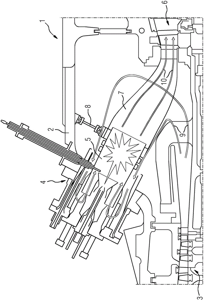
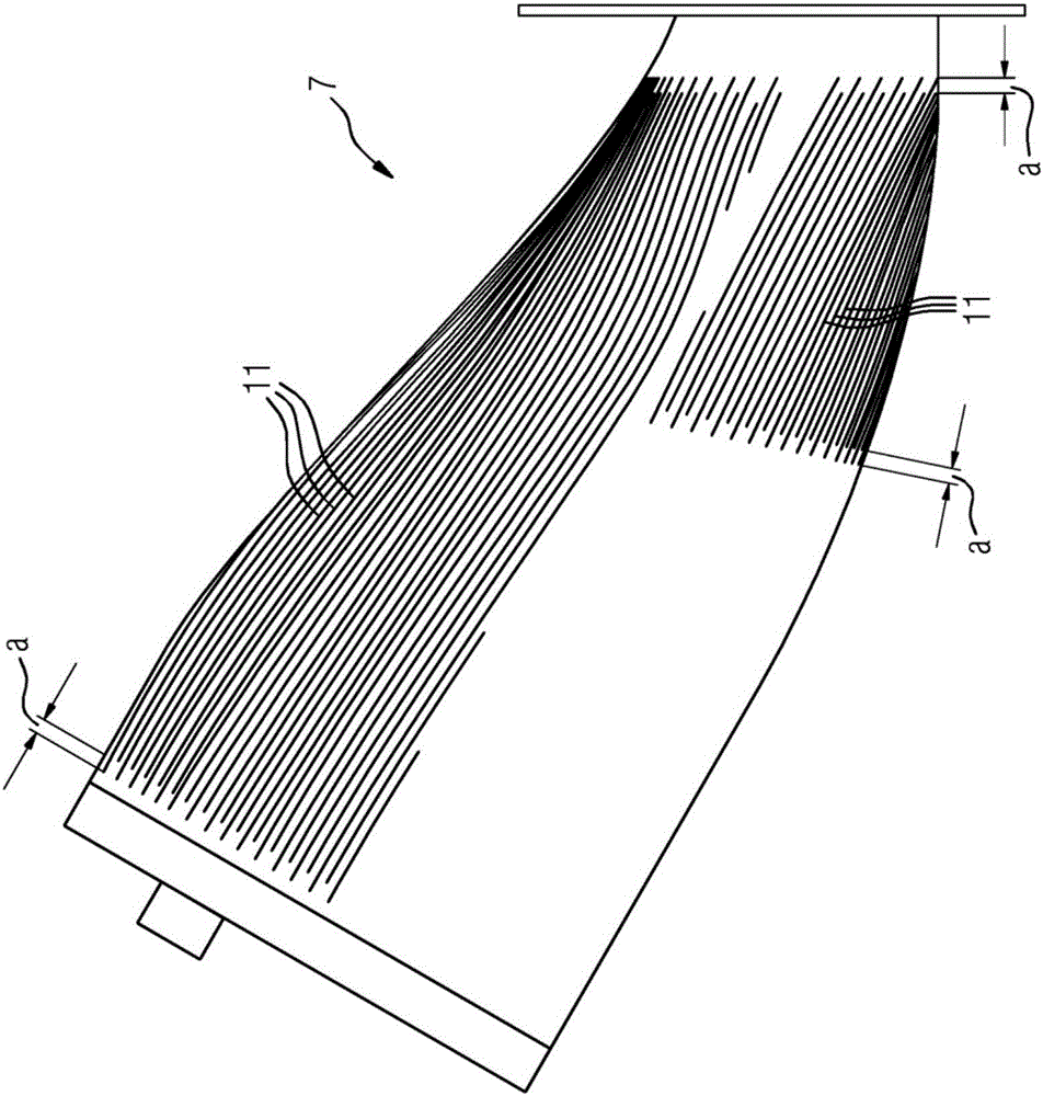
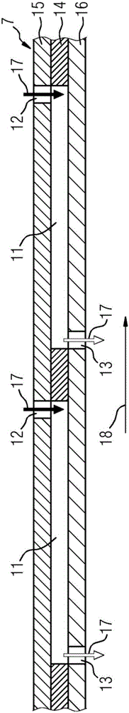
[0032] figure 1 A gas turbine system 1 according to an embodiment of the invention is shown. A gas turbine system 1 includes a multi-part housing 2, a compressor 3 disposed in the housing 2, a combustor device 4 fixed to the housing 2 and provided with a combustion chamber 5, a turbine 6 disposed in the housing 2, and a The transition duct 7 connecting the combustion chamber 5 and the turbine 6 . During assembly of the gas turbine system 1 , the transition duct 7 is connected to the turbine 6 . Furthermore, the transition duct 7 is adjusted and fixed to the housing 2 by means of fixing means 8 . Subsequently, the burner arrangement 4 is inserted into the housing through the associated opening of the housing, whereupon the free end of the combustion chamber 5 enters the transition duct 7 . Subsequently, the combustion chamber 5 and the transition duct 7 are adjusted to each other, and the burner arrangement 4 is fixed to the casing 2 .

[0033] During operation of the gas t...


PUM


Abstract

The present invention relates to a gas turbine system comprising a burner arrangement having a tubular combustion chamber, a turbine and a transition duct (7) connecting the combustion chamber and the turbine, wherein the transition duct (7) is provided with an axially extending cooling air channel (11), wherein the transition duct (7) is provided with a plurality of axially extending cooling air channels (11), and wherein largely each cooling air channel (11) is provided with one single inlet opened to the outside of the transition duct (7) and with one single outlet opened to the inside of the transition duct (7).

Description

technical field [0001] The invention relates to a gas turbine system comprising a burner arrangement having a tubular combustion chamber, a turbine and a transition duct connecting the combustion chamber with the turbine, wherein the transition duct is provided with axially extending cooling air channels. Background technique [0002] Gas turbine systems of the type described above are known in the prior art. During operation, ambient air is compressed and directed towards the burner arrangement. Within the combustor arrangement, compressed air is mixed with fuel and the resulting fuel-air mixture is ignited in the combustion chamber to generate hot combustion gases which are directed via transition ducts towards the turbine. The turbine obtains rotational energy from the hot combustion gases and drives a load, such as a generator. [0003] As operating temperatures increase, cooling of the components of the gas turbine system is generally required to reduce limitations on...

Claims


Application Information

Patent Timeline
Patent Type & Authority Applications(China)
IPC IPC(8): F01D9/02F23R3/00
CPCF01D9/023F01D25/12F02C7/18F05D2260/202F05D2260/204F23R3/002F23R3/005F23R3/02F23R3/04F23R3/06F23R3/08F23R2900/00017F23R2900/03041F23R2900/03042F23R2900/03043F23R2900/03044F23R2900/03045
Inventor 马蒂亚斯·哈泽维迪雅纳森·克里希南保罗·A·桑德斯
Owner SIEMENS ENERGY GLOBAL GMBH & CO KG
Why Eureka
Try Eureka