Bladder detector and using method thereof

A detector and bladder technology, which is applied in the field of bladder detectors, can solve problems such as complex structure and complicated operation, and achieve the effect of simple and compact structure, simple operation and low instrument cost

Pending Publication Date: 2017-05-31
THE AFFILIATED HOSPITAL OF SOUTHWEST MEDICAL UNIV
View PDF7 Cites 0 Cited by
  • Summary
  • Abstract
  • Description
  • Claims
  • Application Information

AI Technical Summary

Problems solved by technology

[0007] Complex structure, complex operation

Method used


Image

  • Bladder detector and using method thereof
  • Bladder detector and using method thereof
  • Bladder detector and using method thereof

Examples


Embodiment 1

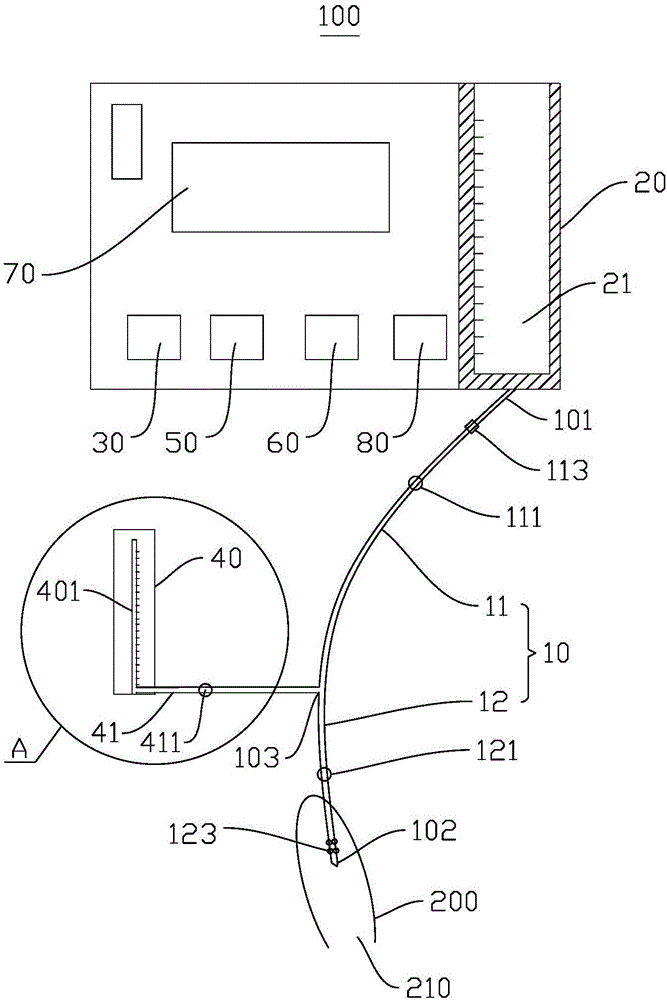
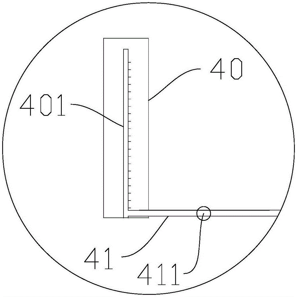
[0043] Please refer to figure 1 , the present embodiment provides a bladder testing instrument 100 , which includes a urinary catheter 10 , a water storage device 20 , a temperature control device 30 and a water column manometer 40 .

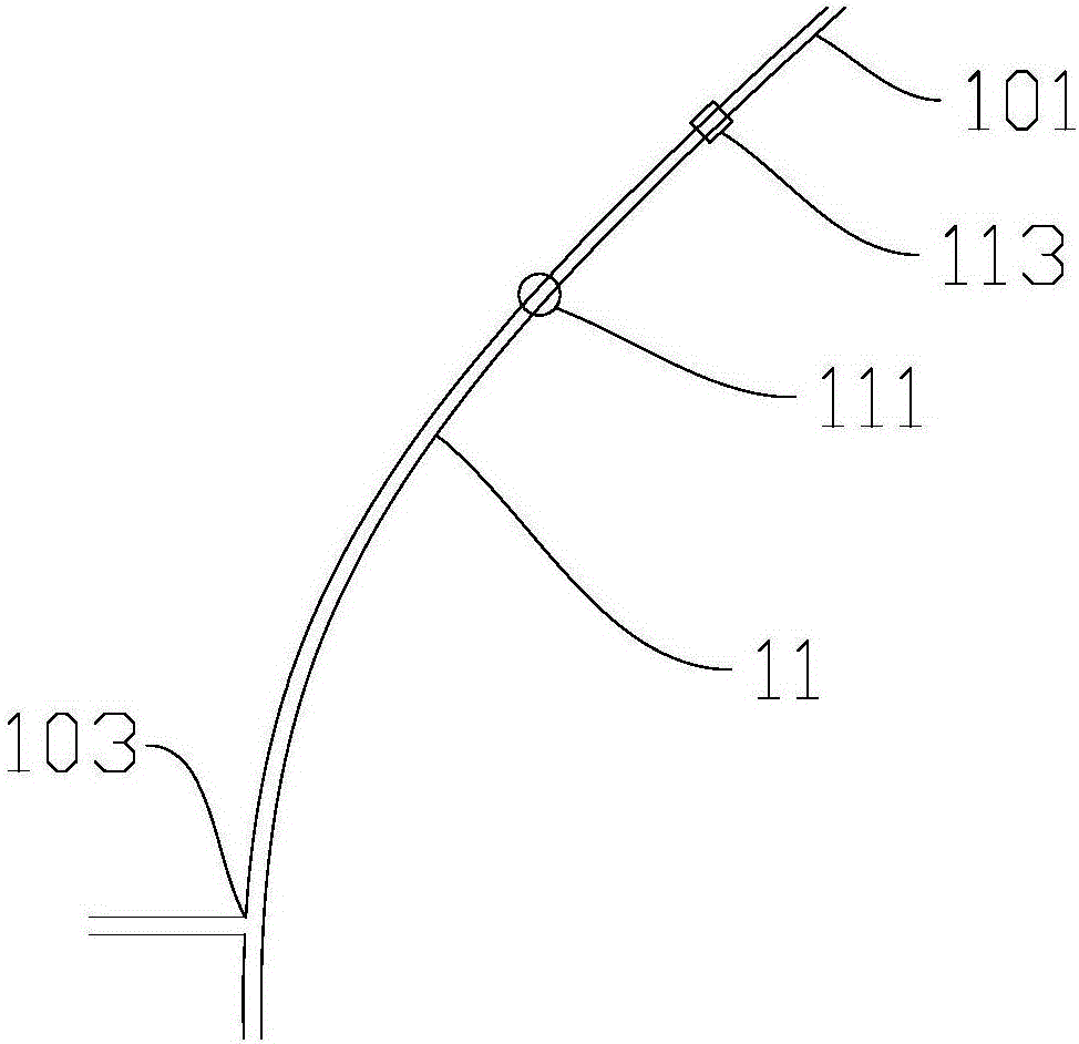
[0044] The water storage device 20 has a water storage chamber 21, the urinary catheter 10 has a first end 101 communicating with the water storage chamber 21 and a second end 102 extending into the human bladder cavity 210, and the urinary catheter 10 is provided near the second end 102 There is a temperature sensor 123 for detecting the temperature in the bladder cavity 210. The middle part of the urinary catheter 10 is provided with a connecting part 103. The urinary catheter 10 is separated by the connecting part 103 into a first tube 11 and a second tube 12 that can be switched on and off. The first end 101 is located on the first pipe 11, and the water column manometer 40 communicates with the connecting part 103 through the connectable co...

Embodiment 2

[0085] This embodiment also provides a method for using the bladder tester 100. For the structure of the bladder tester 100, reference may be made to Example 1, and the disclosed technical solution in Example 1 will not be described again.

[0086] Specifically, it includes the following steps:

[0087] Step S100: Control the switch control device 80 to close the valve on the first tube 11, insert the urinary tube 10 through the urethra, so that the second end 102 is located in the bladder cavity 210 of the human body;

[0088] Step S200: the temperature control device 30 receives the signal output by the temperature sensor 123, and adjusts the water temperature in the water storage chamber 21;

[0089] Step S300: Control the switch control device 80 to open the valve on the first tube 11, so that the water storage chamber 21 and the bladder chamber 210 are in a communication state;

[0090] Step S400: Control the flow rate control device 50 and the flow control device 60, so...

Embodiment 3

[0099] Please refer to Figure 4 This embodiment also provides a method for using the bladder tester 100. For the structure of the bladder tester 100, reference may be made to Example 1, and the disclosed technical solution in Example 1 will not be described again.

[0100] Specifically, the difference between this embodiment and Embodiment 2 is that in step S100, the connecting pipe 41 is removed, the connecting pipe 41 is separated from the urinary pipe 10, and the control switch control device 80 opens the valve on the second pipe 12 to perform urination. Operation.

[0101] The purpose of closing the first valve 111 is to prevent urine from entering the water storage cavity 21 . After the connecting pipe 41 is removed, the second valve 121 is opened, and the urine is discharged from the connecting part 103 through the second pipe 12 .

[0102] If the connecting part 103 adopts a three-way pipe to communicate with the connecting pipe 41, the first pipe 11 and the second pi...


PUM


Abstract

The invention provides a bladder detector and a using method thereof, and belongs to the technical field of medical apparatuses and instruments. The bladder detector comprises a ureter, a water storage device, a temperature control device and a water column pressure gauge, the water storage device is provided with a water storage cavity, the ureter is provided with a first end communicated with the water storage cavity and a second end stretching into the human bladder cavity, a temperature sensor for detecting the temperature inside the bladder cavity is arranged at the position, close to the second end, of the ureter, and the temperature control device is used for receiving a temperature signal output by the temperature sensor and adjusting the water temperature inside the water storage cavity. Operation is easy in the whole testing process. The bladder detector is exquisite and reasonable in design, simple and compact in structure, low in whole detector manufacturing cost, and huge in market application potential; by adopting the using method of the bladder detector, the corresponding effect can be better achieved.

Description

technical field [0001] The invention relates to the technical field of medical devices, in particular to a bladder tester and a method for using the bladder tester. Background technique [0002] Neurogenic bladder dysfunction is seen in various types of nerve paralysis, and is also seen in the elderly and postpartum pelvic floor dysfunction. It is one of the most common dysfunctions and one of the main factors affecting patients' self-esteem and quality of life. Bladder volumetric measurements are the fundamental modality for the assessment and treatment of neurogenic bladders. [0003] At present, the main dysfunction of people after spinal cord injury is bladder dysfunction, specifically manifested as: urinary incontinence and urinary retention. Bladder dysfunction is the weakening or loss of voiding function caused by drugs, cognitive impairment, decreased activity, various neurological diseases, or trauma. Like this, caused the activity of patient's daily life can not ...

Claims


Application Information

Patent Timeline
Patent Type & Authority Applications(China)
IPC IPC(8): A61B5/20A61B5/01
CPCA61B5/01A61B5/202A61B5/204A61B5/205A61B5/6874
Inventor 郭声敏
Owner THE AFFILIATED HOSPITAL OF SOUTHWEST MEDICAL UNIV
Why Eureka
Try Eureka