Multi-grade decelerating light massage machine core with walking component

A walking motor and two-stage deceleration technology, which is applied to kneading and massage appliances, massage auxiliary products, passive exercise equipment, etc., can solve the problems of waste of space, difficulty in applying the movement to miniaturized massage machines, etc., and achieve volume Reduced size, small footprint, and low cost

Pending Publication Date: 2017-05-31
SHANGHAI RONGTAI FITNESS TECH DEV CO LTD
0 Cites 1 Cited by

AI-Extracted Technical Summary

Problems solved by technology

[0003] However, the massage mechanisms on the market generally achieve the final ideal massage speed through the first-stage V-belt deceleration, and then through the...

Abstract

The invention discloses a multi-grade decelerating light massage machine core with a walking component, comprising a walking component and a massage core component; the walking component is fixed with the massage core through a trolley frame, wherein the walking component comprises a core shell and the walking mechanism, and the walking mechanism comprises a first-grade walking deceleration group and a second-grade walking deceleration group; the first-grade walking deceleration group comprises a walking motor (with worm) and a first-grade walking worm; the second-grade walking deceleration group comprises a second-grade walking worm shaft, a second-grade walking worm and a walking spindle; the first-grade walking worm and the second-grade walking worm shaft are positioned and connected through a pin and a bearing and further in driving connection through the meshing of the worm wheel and the worm; the walking motor and the walking shell are fixedly arrange don the connecting plate of the trolley frame; the massage core component comprises a massage motor, a massage mechanism and an outer shell. The multi-grade decelerating light massage machine core is simple and compact in structure, small in space, and can realize the walking kneading massage under a low cost.

Application Domain

Chiropractic devicesSuction-kneading massage

Technology Topic

Electric machineryEngineering +2

Image

  • Multi-grade decelerating light massage machine core with walking component
  • Multi-grade decelerating light massage machine core with walking component
  • Multi-grade decelerating light massage machine core with walking component

Examples

  • Experimental program(1)

Example Embodiment

[0018] In order to make the technical means, creative features, objectives and effects of the present invention easy to understand, the present invention will be further explained below in conjunction with specific embodiments.
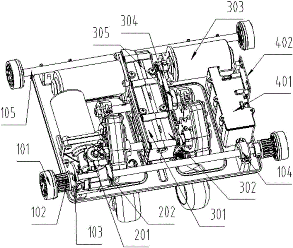
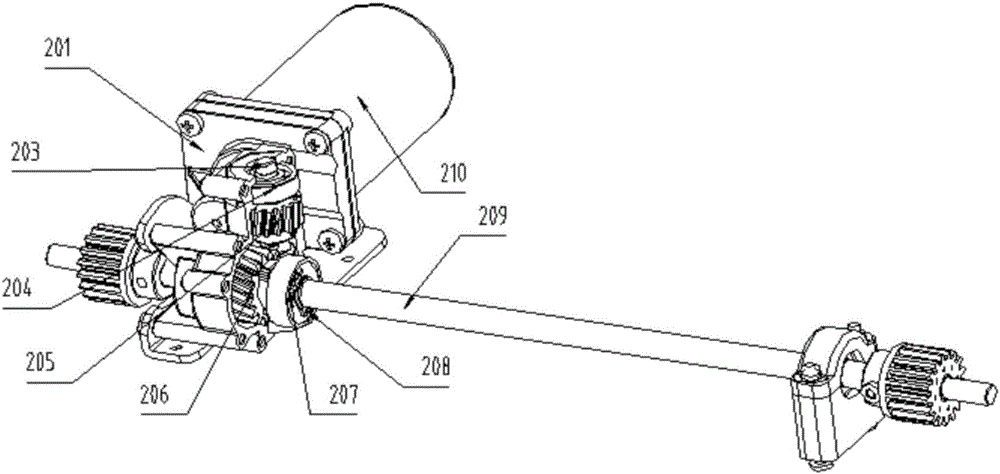
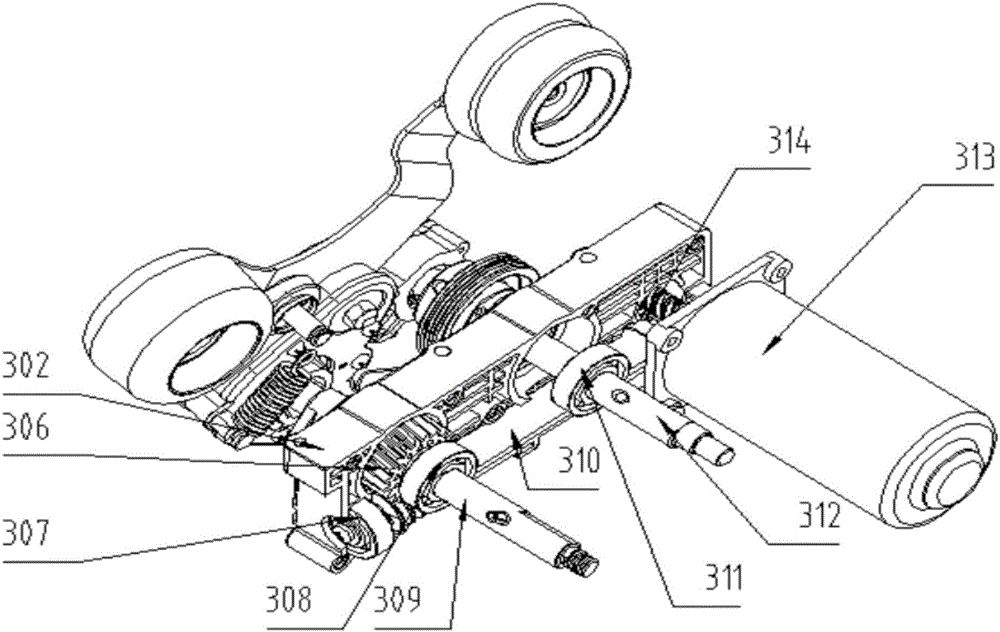
[0019] See Figure 1-Figure 3 , The multi-stage deceleration light and thin massage core with walking components according to the present invention includes a massage core component and a walking component;
[0020] The traveling assembly includes a left traveling housing 201, a right traveling housing 202, a traveling two-stage worm shaft 203, a third bearing 204, a traveling first-stage worm gear 205, a traveling two-stage worm gear 206, a fourth bearing 207, and a circlip 208. Traveling main shaft 209, traveling motor (with worm) 210; traveling motor (with worm) 210 is fixed on the left traveling housing 201.
[0021] The traveling secondary worm shaft 203 is mounted on the left traveling housing 201 and the right traveling housing 202 through a third bearing 204, and the traveling primary worm gear 205 is mounted on the traveling secondary worm shaft 203 through a pin.
[0022] The traveling main shaft 209 is installed on the left traveling housing 201 and the right traveling housing 202 through a fourth bearing 207 and a circlip 208, and the traveling secondary worm gear 206 is installed on the traveling main shaft 209 through a pin.
[0023] The traveling mechanism includes a first-stage traveling reduction group and a second-stage traveling reduction group. The first-stage traveling reduction group includes a traveling motor (with a worm) 210, a traveling first-stage worm gear 205 and a traveling two-stage worm shaft 203. The traveling motor has a worm and a traveling The first-stage worm gear 205 is meshed and connected, the first-stage traveling worm gear 205 and the second-stage traveling worm shaft 203 are fixed by pins, and the second-stage traveling worm shaft 203 is mounted on the left traveling housing 201 and the right traveling housing 202 through a third bearing 204, so The traveling two-stage reduction unit includes a traveling two-stage worm shaft 203, a traveling two-stage worm gear 206, a fourth bearing 207, and a traveling main shaft 209. The traveling two-stage worm gear 206 and traveling main shaft 209 are fixed by a pin shaft and installed by a fourth bearing 207 On the left walking housing 201 and the right walking housing 202. Thus, the power of the traveling motor is transmitted to the traveling shaft 209. The motor shaft of the traveling motor (with a worm) 210 is perpendicular to the traveling secondary worm shaft 203, and the traveling secondary worm shaft 203 is perpendicular to the traveling main shaft 209.
[0024] The massage core assembly includes a left shell 301, a right shell 302, a kneading primary deceleration group and a kneading secondary acceleration group. The kneading primary deceleration group includes a kneading motor (with worm) 313 and a kneading Kneading the primary worm gear 314, kneading the secondary acceleration group includes kneading secondary worm shaft 310 and kneading secondary worm gear 306, kneading secondary worm shaft 310 passes through eighth bearing 308 and left housing 301 and right housing 302 Fixed, the kneading shaft 309 is fixed by the seventh bearing 307 and the kneading secondary worm gear 306. The massage core assembly transmits motion through the engagement of the worm gear and the worm, and then drives the massage ball to swing to realize the massage action. The motor shaft of the kneading motor (with a worm) 313 is perpendicular to the kneading secondary worm shaft 310, and the kneading secondary worm shaft 310 is perpendicular to the kneading shaft 309.
[0025] The basic principles and main features and advantages of the present invention have been shown and described above. Those skilled in the industry should understand that the present invention is not limited by the foregoing embodiments. The foregoing embodiments and descriptions only illustrate the principles of the present invention. Without departing from the spirit and scope of the present invention, the present invention may have Various changes and improvements, these changes and improvements fall within the scope of the claimed invention. The scope of protection claimed by the present invention is defined by the appended claims and their equivalents.

PUM

no PUM

Description & Claims & Application Information

We can also present the details of the Description, Claims and Application information to help users get a comprehensive understanding of the technical details of the patent, such as background art, summary of invention, brief description of drawings, description of embodiments, and other original content. On the other hand, users can also determine the specific scope of protection of the technology through the list of claims; as well as understand the changes in the life cycle of the technology with the presentation of the patent timeline. Login to view more.

Similar technology patents

Automatic box making device and method

ActiveCN105235278AImprove processing speed and productivitysmall footprint
Owner:中科天工(广东)智能技术有限公司

Multistage integrated hydrodynamic cyclone separator

InactiveCN102512857ASmall footprintEasy to install and control
Owner:BEIJING UNIVERSITY OF CIVIL ENGINEERING AND ARCHITECTURE

Garbage leachate advanced treatment method and Fenton reaction tower

ActiveCN103880253ASmall footprintLess investment in infrastructure
Owner:深圳市百斯特环保工程有限公司

Automatic processing production line for metal sheets

ActiveCN105458718ASmall footprintReasonable production beat matching
Owner:江苏扬力数控机床有限公司

Classification and recommendation of technical efficacy words

  • small footprint
  • reduce volume

Implant release mechanism

ActiveUS20080140178A1reduce volumereduce outer diameter
Owner:COOK MEDICAL TECH LLC

Speed reduction box for turbine fracturing

Owner:YANTAI JEREH PETROLEUM EQUIP & TECH

Miniature and Multi-Band RF Coil Design

ActiveUS20100090824A1reduce volumelong wavelength
Owner:HONG KONG APPLIED SCI & TECH RES INST

Automatic washing and dewatering combined device of rotary type mop

InactiveCN102370447Areduce volumeSimple structure
Owner:上海祥美网络科技有限公司 +1

Optical imaging system

ActiveUS20070008625A1reduce volumedeteriorate with time
Owner:SAMSUNG ELECTRONICS CO LTD
Why Eureka
Try Eureka