Coordinate calibration method for micro-injection system on basis of robot assistance

A robot-assisted microinjection technology, which is applied in the direction of hypodermic injection devices, can solve the problem of low efficiency of needle point movement and positioning, and achieve the effect of improving work efficiency and high measurement accuracy

Active Publication Date: 2017-05-31
HARBIN INST OF TECH
View PDF8 Cites 12 Cited by
  • Summary
  • Abstract
  • Description
  • Claims
  • Application Information

AI Technical Summary

Problems solved by technology

[0003] The purpose of the present invention is to solve the problem of low efficiency of needle point movement and positioning in the existing microinjection system, and propose a coordinate calibration method for a robot-assisted microinjection system

Method used


Image

  • Coordinate calibration method for micro-injection system on basis of robot assistance
  • Coordinate calibration method for micro-injection system on basis of robot assistance
  • Coordinate calibration method for micro-injection system on basis of robot assistance

Examples


specific Embodiment approach 1

[0030] The coordinate calibration method of the robot-assisted microinjection system of the present embodiment, such as Figure 5 As shown, the method is realized through the following steps:

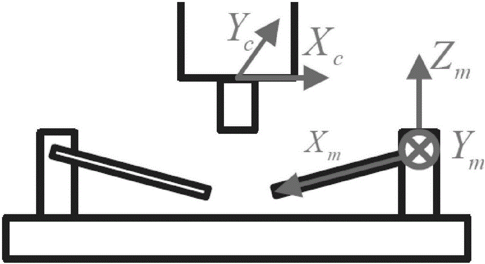
[0031] Step 1: Set the coordinate system of the microscope stage as O s -X s Y s Z s , origin O s is the initial position; the camera coordinate system is O c -X c Y c Z c , point O c Located in the center of the objective lens of the microscope, Z c is the optical axis of the microscope; the coordinate system of the three-degree-of-freedom manipulator is O m -X m Y m Z m ; The coordinate system of the calibration bitmap image plane is O i -UV, origin O i in the upper left corner of the image; and make sure:

[0032] The coordinate transformation matrix between the three-degree-of-freedom manipulator coordinate system and the camera coordinate system is Then the conversion relationship between the three-degree-of-freedom manipulator coordinate system and the camera coo...

specific Embodiment approach 2

[0048] The difference from the specific embodiment 1 is that the coordinate calibration method of the robot-assisted microinjection system in this embodiment is determined as described in step 1:

[0049] The coordinate transformation matrix between the three-degree-of-freedom manipulator coordinate system and the camera coordinate system is Then the conversion relationship between the three-degree-of-freedom manipulator coordinate system and the camera coordinate system is:

[0050] The coordinate transformation matrix between the calibration bitmap image plane coordinate system and the camera coordinate system is Then the conversion relationship between the calibration bitmap image plane coordinate system and the camera coordinate system is: as well as

[0051] The coordinate transformation matrix between the three-degree-of-freedom manipulator coordinate system and the calibration bitmap image plane coordinate system is Then the conversion relationship between the ...

specific Embodiment approach 3

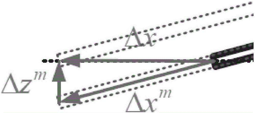
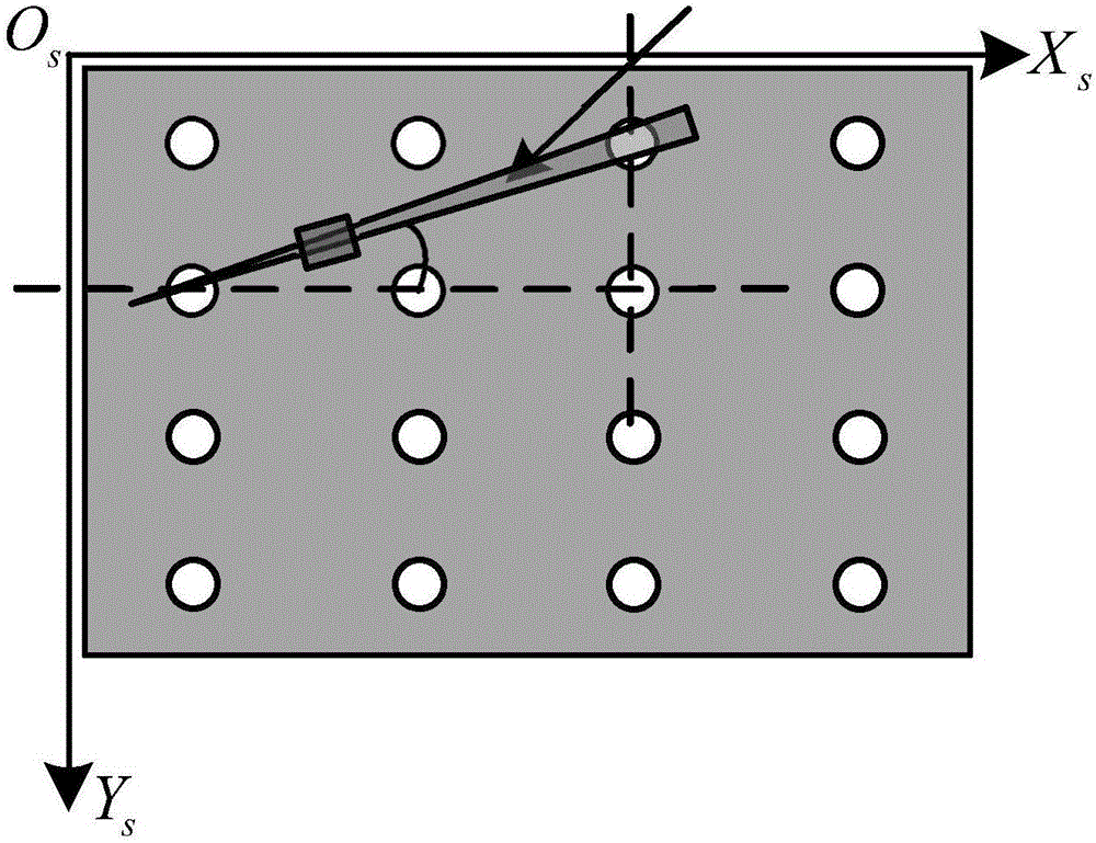
[0060] The difference from Embodiment 1 or Embodiment 2 is that in the coordinate calibration method of the robot-assisted microinjection system in this embodiment, the process of calculating the time for the mechanical arm to complete movement in the field of view described in step 2 is as follows: When moving between two adjacent horizontal, vertical or oblique calibration points in the field of view, the moving distances in the direction of the horizontal u-axis and the longitudinal v-axis are Δx and Δy respectively, and the points in the field of view The array has n in the direction of the horizontal u-axis and the vertical v-axis respectively 1 and n 2 points, such as Figure 4 shown, and

[0061] Horizontal u-axis direction, such as calibration point 1→2, the mechanical arm between two adjacent points is at x m 、y m ,z m The distance to move in each direction:

[0062] x m = Δy cos γ, y m = Δy sin γ, z m =Δy cosγtanα;

[0063] Longitudinal v-axis direction, su...


PUM


Abstract

The invention relates to a coordinate calibration method for a micro-injection system on the basis of robot assistance and belongs to the field of the coordinate calibration method for the micro-injection system. A present micro-injection system has a problem of low efficiency of needle moving and positioning. The coordinate calibration method for the micro-injection system on the basis of robot assistance comprises the following steps: selecting M points from a dot matrix in a present view area as calibration points; operating a mechanical arm according to the preset time and the optimal route; causing a needle point pass by the calibration points and acquiring a clear image; moving an objective table to a next view area; repeating the above steps, completing N view areas and recording a mechanical arm coordinate corresponding to a midpoint in a No.j view area; calculating a coordinate transformation matrix; adopting an expected needle point coordinate and the coordinate transformation matrix for calculating the corresponding mechanical arm coordinate; and then moving the mechanical arm and moving the needle point of a micropipette to an expected position. The coordinate calibration method provided by the invention has the advantages of capability of avoiding the problem of repeated positioning, accurate positioning and high working efficiency.

Description

technical field [0001] The invention relates to a coordinate calibration method of a robot-assisted microinjection system. Background technique [0002] During the microinjection process, the first step is to move the needle tip to a specific position for subsequent manipulations. Compared with manual positioning, the existing automatic needle point positioning method saves time, but the efficiency still needs to be improved. In fact, if the installation position of the mechanical arm and the stage does not change, there is no need to reposition the needle tip, and it is only necessary to calibrate the relationship of several coordinates in the microinjection system in advance. According to this actual need, the present invention designs a calibration method along the time-optimized route. Contents of the invention [0003] The purpose of the present invention is to solve the problem of low efficiency of needle point movement and positioning in the existing microinjectio...

Claims


Application Information

Patent Timeline
Patent Type & Authority Applications(China)
IPC IPC(8): A61M5/00
Inventor 高会军庄松霖林伟阳张格非叶超尚忻忻
Owner HARBIN INST OF TECH
Why Eureka
Try Eureka