Supercharge Your Innovation With Domain-Expert AI Agents!

Carbon strong kneading cylinder body

A kneading and cylinder technology, which is applied to mixers, mixers with rotating stirring devices, transportation and packaging, etc., can solve the problems of large installation space, impossibility of use, poor kneading effect, etc., and achieve smooth feeding process and increased The area of ​​heat exchange and the effect of improving the kneading effect

Active Publication Date: 2017-05-31
YANTAI HUAPENG MACHINERY
View PDF9 Cites 2 Cited by
  • Summary
  • Abstract
  • Description
  • Claims
  • Application Information

AI Technical Summary

Problems solved by technology

The defect of the existing kneading cylinder is that the paste is only squeezed when it is at the bottom of the cylinder, and is not squeezed when it moves to the top of the mixing knife, and the kneading effect is poor
[0004] On the other hand, the invention patent with the publication number CN102389731A discloses a pressurized kneader, which uses a hydraulic drive device to drive the pressurized pot cover to move up and down to apply additional pressure to the material and compact the material to improve the kneading effect. The disadvantages are: (1) The structure is complex: the pressurizing device includes a pressurized pot cover, a hydraulic drive device, and the hydraulic drive device includes a hydraulic pump, an upper beam, a piston rod, a column, a hydraulic cylinder, hydraulic cylinder upper and lower lugs, and a hydraulic pump, etc. ; (2) The installation space of the equipment is large: the volume of the pressurizing device and its running stroke require a large space. Taking the kneading equipment with an effective volume of 2000L as an example, its height is about twice that of the existing ordinary kneading equipment; (3 ) The power of the corresponding configuration is huge: taking the kneading equipment with an effective volume of 2000L as an example, the driving power of the ordinary kneading equipment is 55kW, while the power of the pressurized kneading machine is 250kW, which is nearly 5 times that of the ordinary kneading equipment
Moreover, if the existing ordinary kneader is modified to enhance the kneading effect, due to the limitation of the modification cost and equipment installation space, it is impossible to adopt the pressurized kneader technical solution announced by CN102389731A

Method used


Image

  • Carbon strong kneading cylinder body

Examples


Embodiment Construction

[0018] The technical scheme of the present invention is described in detail below in conjunction with accompanying drawing:

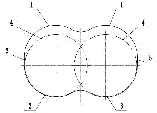
[0019] Such as figure 1 , a carbon strong mixing and kneading cylinder body, each of the left and right mixing knives 4 is installed in the cylinder body, and the axes of the mixing knives 4 are all moving forward and backward, and are used to stir the paste;

[0020] The cross-sectional profile of the inner wall of the cylinder in the front-back direction includes an upper extrusion kneading arc section located above the mixing knife 4 and a lower extrusion kneading arc section located below the mixing knife 4;

[0021] The upper extrusion kneading arc section is provided with two concave upper arc sections 1 corresponding to the two mixing knives 4 one by one;

[0022] The lower extrusion kneading arc section is provided with two concave lower arc sections 3 corresponding to the two mixing knives 4 one by one.

[0023] The gap between the upper arc ...


PUM


Abstract

The invention discloses a carbon strong kneading cylinder body. A right stirring blade (4) and a left stirring blade (4) are installed in the cylinder body, the axial lines of the stirring blades (4) are both forward and backward in direction, the section configuration of the inner wall of the cylinder body in the forward and backward direction comprises an upper extruding and kneading arc section above the stirring blades (4) and a lower extruding and kneading arc section below the stirring blades (4); two inwardly-dished upper circular arc sections (1) in one-to-one correspondence with the two stirring blades (4) are arranged on the upper extruding and kneading arc section; and two inwardly-dished lower circular arc sections (3) in one-to-one correspondence with the two stirring blades (4) are arranged on the lower extruding and kneading arc section. The carbon strong kneading cylinder body can enable a thickener to be extruded both at the bottom and top of the cylinder body, improves the kneading effect and efficiency, and simultaneously also has the advantages of large heat exchange area, convenient processing and use, and the like.

Description

technical field [0001] The invention relates to a kneading cylinder used for kneading paste. Background technique [0002] In the production process of carbon products, the kneading paste is mainly completed by stirring and extruding in the kneading cylinder. [0003] The kneading cylinder in the prior art mainly includes a body and a top cover. The bottom of the body is U-shaped or arc-shaped that matches the outer circle of the mixer blade. The top of the body is a rectangular opening, and the top cover covers the opening. There is a large gap between the top cover and the mixing knife. After the paste is added, the mixing knife rotates to mix the paste. At the same time, when the paste is stirred to the bottom of the cylinder, it is squeezed by the mixing knife and the cylinder to achieve a kneading effect. The defect of the existing kneading cylinder is that the paste is only squeezed when it is at the bottom of the cylinder, and is not squeezed when it moves to the top...

Claims


Application Information

Patent Timeline
Patent Type & Authority Applications(China)
IPC IPC(8): B01F7/04B01F15/00C01B32/05
CPCB01F27/2322B01F27/706B01F35/50
Inventor 王毅王世乃
Owner YANTAI HUAPENG MACHINERY
Features
  • R&D
  • Intellectual Property
  • Life Sciences
  • Materials
  • Tech Scout
  • Unparalleled Data Quality
  • Higher Quality Content
  • 60% Fewer Hallucinations
Learn More