Catalytic reaction tank for sewage treatment
A catalytic reaction and sewage treatment technology, which is applied in water/sewage treatment, oxidized water/sewage treatment, water/sludge/sewage treatment, etc. It can solve the problems of catalyst and sewage affecting reaction efficiency, easy enrichment, and inapplicability. , to achieve the effect of convenient and full mixing, improving reaction efficiency, convenient collection and replacement
- Summary
- Abstract
- Description
- Claims
- Application Information
AI Technical Summary
Problems solved by technology
Method used
Image
Examples
Embodiment 1
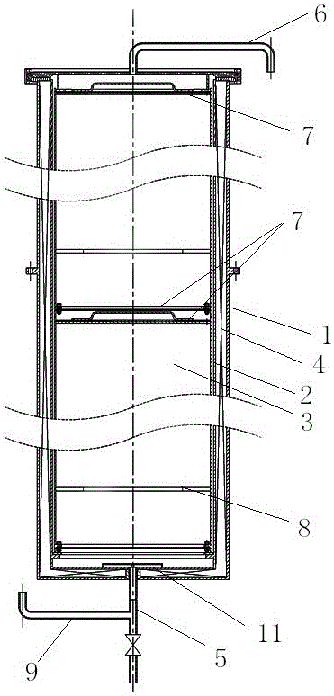
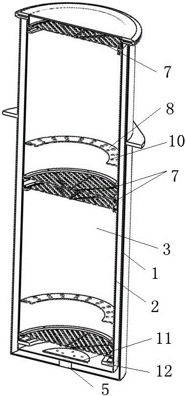
[0016] Embodiment 1: as figure 1 with 2 Shown is a catalytic reaction tank for sewage treatment, the catalytic reaction tank is a cylindrical cylinder structure, the cylinder structure is composed of a cylindrical shell 1 and a cylindrical inner tank 2, An insulating layer 4 is provided between the shell 1 and the inner tank 2, the top of the cylinder is provided with a discharge pipe 6, and the bottom of the cylinder is provided with a feed pipe 5, and the inner tank 2 is movable and installed with multiple Catalyst reaction barrel 3, described catalyst reaction barrel 3 is made up of upper and lower two circular screen mesh end faces 7 and cylindrical barrel wall, and the diameter of barrel wall matches the inner diameter of liner 2, and described catalytic reaction An annular baffle 8 is provided on the inner wall of the barrel 3, and a plurality of longitudinally installed baffle flow holes 10 are evenly distributed on the baffle 8.
Embodiment 2
[0017] Embodiment 2: as figure 1 with 2 As shown, the feed pipe 5 is provided with a feed valve and a branch pipeline 9, and the branch pipeline 9 is an emptying pipe; after the overall reaction is completed, the catalyst reaction barrel 3 is taken out from the inner tank 2, and the inner tank is The residual liquid in 2 needs to be emptied through the emptying pipe 9 to facilitate the cleaning and maintenance of the inside of the tank.
Embodiment 3
[0018] Embodiment 3: as figure 1 with 2 As shown, the bottom of the liner 2 is provided with a circular flow divider 11, the bottom of the flow divider 11 is connected to the feed pipe 5, and the top of the flow divider 11 is provided with a plurality of flow openings; The bottom of the barrel 3 is connected to facilitate sufficient contact between the sewage and the catalyst stored in the catalytic reaction barrel 3 and improve the reaction efficiency.
PUM
 Abstract
Description
Claims
Application Information
 - R&D
- Intellectual Property
- Life Sciences
- Materials
- Tech Scout
- Unparalleled Data Quality
- Higher Quality Content
- 60% Fewer Hallucinations
Browse by: Latest US Patents, China's latest patents, Technical Efficacy Thesaurus, Application Domain, Technology Topic, Popular Technical Reports.
© 2025 PatSnap. All rights reserved.Legal|Privacy policy|Modern Slavery Act Transparency Statement|Sitemap|About US| Contact US: help@patsnap.com


