Caking fertilizer crushing device for agriculture big data

A crushing device and big data technology, applied in grain processing, etc., can solve the problems of poor crushing effect, low work efficiency, complicated operation, etc., achieve good effect, improve work efficiency, and simple operation

Active Publication Date: 2017-05-31
安徽众力农业装备科技有限公司
8 Cites 29 Cited by

AI-Extracted Technical Summary

Problems solved by technology

[0005] In order to overcome the shortcomings of poor crushing effect, complicated operation and low work efficiency of the current waste crushing device, the technical problem to be solv...

Method used

Principle of work: when using the present invention, the agglomerated fertilizer is first poured in the lower hopper 9, and the agglomerated fertilizer falls between the right splint 10 and the left splint 11 by the lower hopper 9. Start the first motor 15 to rotate, the first motor 15 drives the first pulley 17 to rotate and the disk 18 to rotate, and the disk 18 rotates to drive the first connecting rod 13 and the second connecting rod 14 to swing up and down through the third connecting rod 16. Under the action of the first connecting rod 13 and the second connecting rod 14, the right clamping plate 10 is swung, at this time, the agglomerated fertilizer between the right clamping plate 10 and the left clamping plate 11 is crushed, and the crushed agglomerated fertilizer falls into the crushing box Within 19. The first pulley 17 rotate...

Abstract

The invention belongs to the technical field of agriculture big data, and particularly relates to a caking fertilizer crushing device for agriculture big data and aims at achieving the technical purpose of providing the caking fertilizer crushing device for the agriculture big data, wherein the caking fertilizer crushing device is good in crushing effect, easy to operate and high in work efficiency. To achieve the above technical purpose, the caking fertilizer crushing device for the agriculture big data is provided and comprises a bottom plate, a left support, a first collecting frame, a second collecting frame, a supporting frame, a right support, a screen, a top plate, a discharging hopper, a right clamping plate, a left clamping plate, grinding teeth and the like. The left support, the first collecting frame, the second collecting frame, the supporting frame and the right support are sequentially welded to the bottom plate from left to right. According to the provided caking fertilizer crushing device for the agriculture big data, caking fertilizer is crushed firstly through the right clamping plate and the left clamping plate, and a crushing cutter and a crushing hammer conduct cutting and hammering on the crushed caking fertilizer at the same time.

Application Domain

Technology Topic

Image

  • Caking fertilizer crushing device for agriculture big data
  • Caking fertilizer crushing device for agriculture big data
  • Caking fertilizer crushing device for agriculture big data

Examples

  • Experimental program(1)

Example Embodiment

[0026] Example 1
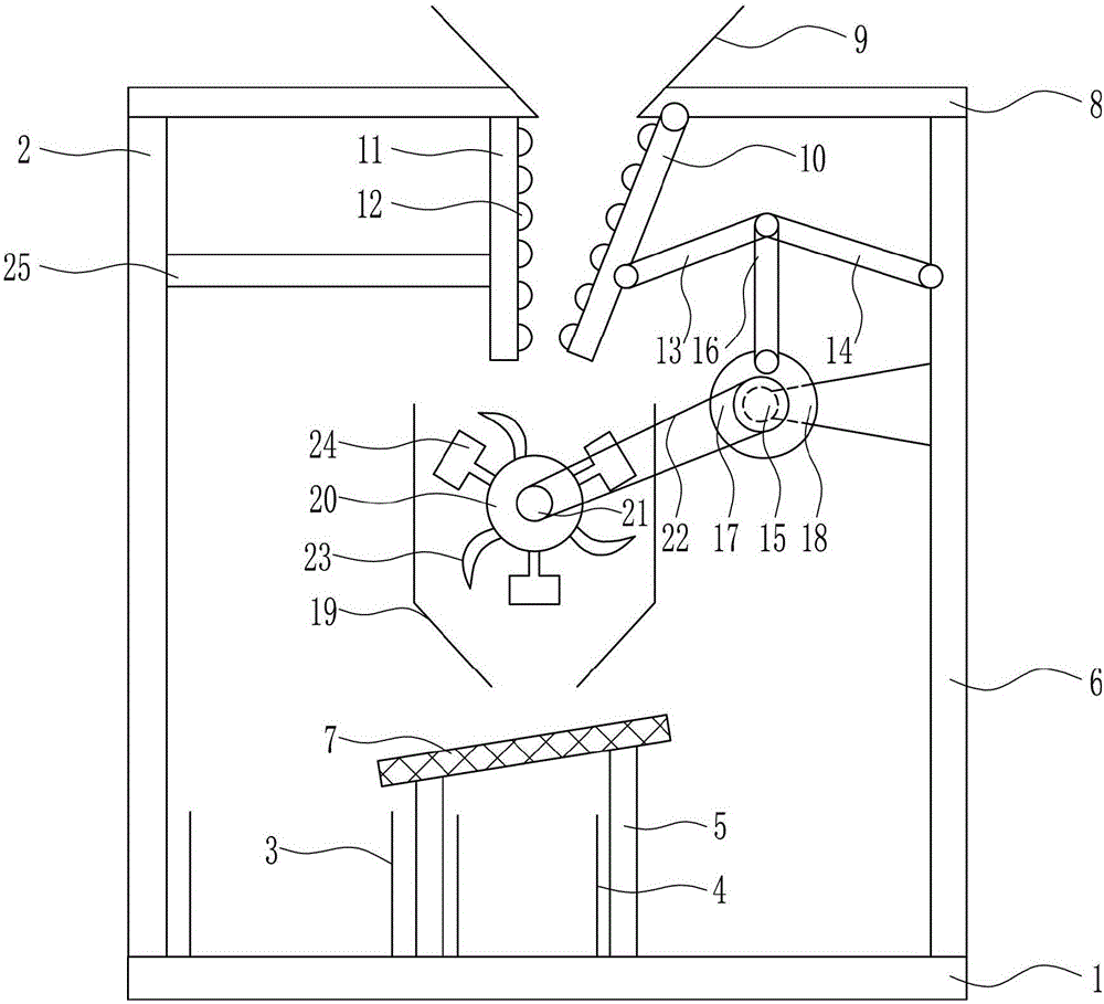
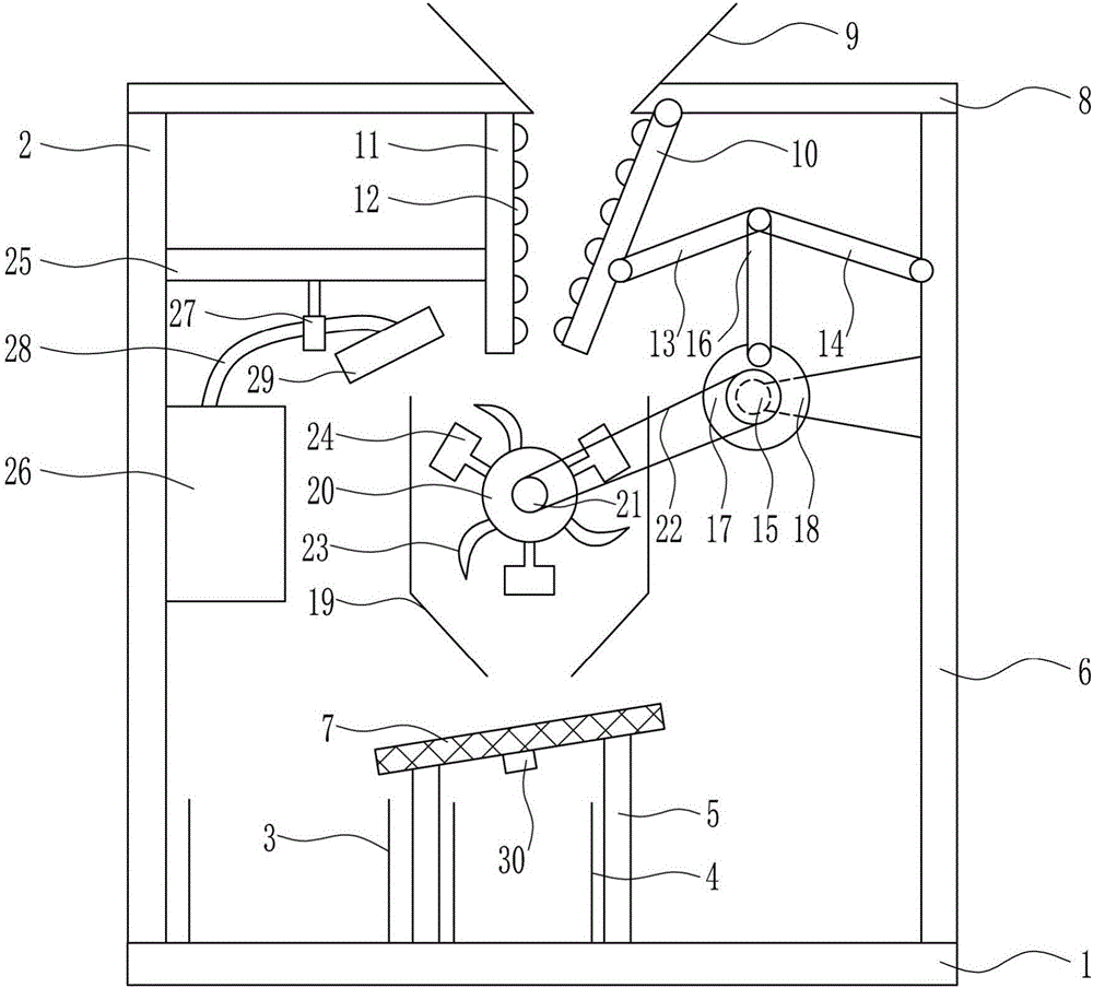
[0027] An agglomerated fertilizer crushing device for agricultural big data, such as Figure 1-3 As shown, it includes a bottom plate 1, a left bracket 2, a first receiving frame 3, a second receiving frame 4, a support frame 5, a right bracket 6, a screen 7, a top plate 8, a lower hopper 9, a right splint 10, and a left Splint 11, gear grinding 12, first connecting rod 13, second connecting rod 14, first motor 15, third connecting rod 16, first pulley 17, disc 18, crushing box 19, crushing roller 20, second pulley 21. Flat belt 22, crushing knife 23, crushing hammer 24 and support rod 25. The bottom plate 1 is welded from left to right with left bracket 2, first receiving frame 3, second receiving frame 4, support frame 5 and The right support 6, the support frame 5 is symmetrically and vertically arranged on the left and right sides, the second receiving frame 4 is located between the two support frames 5, the top of the support frame 5 is welded with a screen 7, which is low left and high right, The second receiving frame 4 is located directly below the screen 7, and the first receiving frame 3 is located at the bottom left of the screen 7. The top of the left bracket 2 and the right bracket 6 is welded horizontally with a top plate 8, and the top of the top plate 8 is welded with a lower hopper in the middle 9. The left side of the top plate 8 is vertically welded with a left splint 11, the bottom right of the top plate 8 is hingedly connected with a right splint 10, the right side of the left splint 11 and the left side of the right splint 10 are welded with grinding teeth 12, the right splint 10 is provided with a first connecting rod 13 on the right side, one end of the first connecting rod 13 is hingedly connected with the right splint 10, and the left side of the right bracket 6 is provided with a second connecting rod 14 and a first motor 15, the first motor 15 is connected with The right bracket 6 is connected by bolt connection, the second link 14 is located above the first motor 15, one end of the second link 14 is hingedly connected to the right bracket 6, and the other end of the second link 14 is connected to the first link The other end of 13 is hingedly connected, the output shaft of the first motor 15 is connected with a first pulley 17 through a coupling, the first pulley 17 is located on the front side of the first motor 15, and the first pulley 17 is provided with a disc 18 on the front side, The disc 18 is provided with a third link 16 at an eccentric position. One end of the third link 16 is hingedly connected with the disc 18, and the other end of the third link 16 is hinged with the second link 14 and the first link 13 The second connecting rod 14 and the first connecting rod 13 and the third connecting rod 16 are connected by a composite hinge. A crushing box 19 is provided directly above the screen 7, and the middle part of the crushing box 19 is connected by bolts. There is a crushing roller 20. The front side of the crushing roller 20 is connected with a second pulley 21 by a key connection. A flat belt 22 is connected between the second pulley 21 and the first pulley 17, and a number of crushing knives 23 are welded on the crushing roller 20. With several crushing hammers 24, the crushing knife 23 and the crushing hammer 24 are interlaced with each other. The right side of the left support 2 is horizontally welded with a support rod 25, and the right end of the support rod 25 is welded to the left side of the left splint 11.
[0028] It also includes a vacuum cleaner 26, a guide sleeve 27, a dust suction pipe 28 and a suction nozzle 29. The right side of the left bracket 2 is connected to the vacuum cleaner 26 by bolt connection. The bottom of the support rod 25 is vertically welded with a guide sleeve 27 and a guide sleeve 27. There is a suction pipe 28 inside. One end of the suction pipe 28 is connected to the top of the vacuum cleaner 26 through a flange connection, and the other end of the suction pipe 28 is connected with a suction nozzle 29 through a flange connection. The suction nozzle 29 is connected to the vacuum cleaner. 26 communicate with each other through the dust suction pipe 28.
[0029] The vibration exciter 30 is also included, and the vibration exciter 30 is connected in the middle of the bottom of the screen 7 by screws.
[0030] The first motor 15 is a servo motor.
[0031] The material of the bottom plate 1 is Q235 steel.
[0032] The material of the first receiving frame 3 and the second receiving frame 4 is stainless steel.
[0033] Working principle: When using the present invention, the agglomerated fertilizer is first poured into the lower hopper 9 and the agglomerated fertilizer falls between the right splint 10 and the left splint 11 through the lower hopper 9. Start the first motor 15 to rotate. The first motor 15 drives the first pulley 17 to rotate and the disk 18 to rotate. The disk 18 rotates through the third link 16 to drive the first link 13 and the second link 14 to swing up and down. Under the action of a connecting rod 13 and a second connecting rod 14, the right splint 10 swings. At this time, the agglomerated fertilizer between the right splint 10 and the left splint 11 is crushed, and the crushed agglomerated fertilizer falls into the crushing box. Within 19. The rotation of the first pulley 17 drives the second pulley 21 to rotate through the flat belt 22. The second pulley 21 drives the crushing roller 20 to rotate. The crushing knife 23 and the crushing hammer 24 rotate accordingly to cut and beat the crushed agglomerated fertilizer. The crushed agglomerated fertilizer can be crushed, and the work efficiency is high. The crushed agglomerated fertilizer will fall on the screen 7, the completely crushed agglomerated fertilizer will fall into the second receiving frame 4 through the screen 7, and the incompletely crushed agglomerated fertilizer will fall into the second receiving frame 4 through the screen 7. In a receiving frame 3, the agglomerated fertilizer falling into the first receiving frame 3 can be crushed again. After the crushing is completed, the first motor 15 can be turned off.
[0034] Because it also includes a vacuum cleaner 26, a guide sleeve 27, a dust suction pipe 28 and a suction nozzle 29, the right side of the left bracket 2 is connected to the vacuum cleaner 26 by bolt connection, and the bottom of the support rod 25 is vertically welded with a guide sleeve 27, the guide sleeve 27 is provided with a suction pipe 28, one end of the suction pipe 28 is connected to the top of the vacuum cleaner 26 through a flange connection, and the other end of the suction pipe 28 is connected with a suction nozzle 29 through a flange connection. The vacuum cleaners 26 communicate with each other through the dust suction pipe 28. The guide sleeve 27 can fix the position of the dust suction pipe 28. In the process of crushing the agglomerated fertilizer, more dust may be raised. The vacuum cleaner 26 is started, and the vacuum cleaner 26 works through the suction nozzle 29 to suck dust from the dust suction pipe 28 In the vacuum cleaner 26, this phenomenon is avoided.
[0035] Because it also includes an exciter 30, the bottom of the screen 7 is connected with an exciter 30 through a screw, and the exciter 30 is started to vibrate. The exciter 30 drives the screen 7 to vibrate, so that it can fall on the screen 7 and be crushed. The latter agglomerated fertilizer better falls into the first receiving frame 3 or the second receiving frame 4.
[0036] Because the first motor 15 is a servo motor, the servo motor can better control the speed and make the operation more stable.
[0037] Because the base plate 1 is made of Q235 steel, the Q235 steel has a large load-bearing capacity and is not easy to corrode, which increases the service life of the base plate 1.
[0038] Because the material of the first receiving frame 3 and the second receiving frame 4 is stainless steel, the stainless steel is acid-resistant and not easy to corrode, so that the first receiving frame 3 and the second receiving frame 4 are not easy to rust under the condition of long-term use. Durable.

PUM

no PUM

Description & Claims & Application Information

We can also present the details of the Description, Claims and Application information to help users get a comprehensive understanding of the technical details of the patent, such as background art, summary of invention, brief description of drawings, description of embodiments, and other original content. On the other hand, users can also determine the specific scope of protection of the technology through the list of claims; as well as understand the changes in the life cycle of the technology with the presentation of the patent timeline. Login to view more.

Similar technology patents

Classification and recommendation of technical efficacy words

  • Improve work efficiency
  • Good effect

Improved novel energy automobile charging device

Owner:XIAMEN YINLV JIEYUAN ENVIRONMENTAL PROTECTION TECH CO LTD

Full-automatic water-drill grinding and polishing machine

InactiveCN101758433AImprove work efficiencyFixture positioning is accurateEdge grinding machinesManipulatorEngineering
Owner:瑞安市天成包装机械有限公司

Hyperlipemia therapeutic agent

ActiveUS20050187292A1Good effectBiocideMetabolism disorderEPA - Eicosapentaenoic acidHyperlipidemia
Owner:KOWA CO LTD +1
Why Eureka
Try Eureka