Powder spraying mechanism

A spraying mechanism and powder technology, applied in the direction of coating, liquid coating device on the surface, etc., can solve the problems of affecting the personal safety of the operator, reducing the work efficiency of the enterprise, and high labor intensity, etc., to achieve stable and reliable structure, convenient and convenient The effect of material and assembly, simplified structure

Inactive Publication Date: 2017-05-31
天津市瑞森金属制品有限公司
View PDF0 Cites 0 Cited by
  • Summary
  • Abstract
  • Description
  • Claims
  • Application Information

AI Technical Summary

Problems solved by technology

[0002] After the machining of mechanical parts, in order to improve the product performance of the parts or facilitate storage and transportation, it is often necessary to carry out subsequent process treatments on the parts, such as nitriding or nitriding treatment, to improve the wear resistance of the parts surface, and to spray anti-rust layers Or smear butter, etc., to achieve anti-corrosion and oxidation, to facilitate the storage and transportation of parts, to ensure that the processed surface is oxidized or corroded during storage, which affects the product performance of parts, and the processing level of post-processing directly affects the use or assembly of parts. The quality and precision of the links are therefore very important. At present, in terms of parts processing, the most common anti-corrosion and anti-rust process is to coat the anti-rust layer. At present, the common coating devices are mostly manual, with low work efficiency and labor The strength is high, and the coated powder is mostly volatile, and it will cause certain harm to the human body after inhalation. If things go on like this, it will affect the personal safety of the operator and reduce the work efficiency of the enterprise. The coating of the standard product is not applicable, and for enterprises with a small amount of coating, the cost of purchasing a coating production line is too high, and the utilization rate is low

Method used


Image

  • Powder spraying mechanism
  • Powder spraying mechanism
  • Powder spraying mechanism

Examples


Embodiment Construction

[0023] It should be noted that, in the case of no conflict, the embodiments of the present invention and the features in the embodiments can be combined with each other.

[0024] In describing the present invention, it should be understood that the terms "center", "longitudinal", "transverse", "upper", "lower", "front", "rear", "left", "right", " The orientations or positional relationships indicated by "vertical", "horizontal", "top", "bottom", "inner" and "outer" are based on the orientations or positional relationships shown in the drawings, and are only for the convenience of describing the present invention and Simplified descriptions, rather than indicating or implying that the device or element referred to must have a particular orientation, be constructed and operate in a particular orientation, and thus should not be construed as limiting the invention. In addition, the terms "first", "second", etc. are used for descriptive purposes only, and should not be understood ...


PUM


Abstract

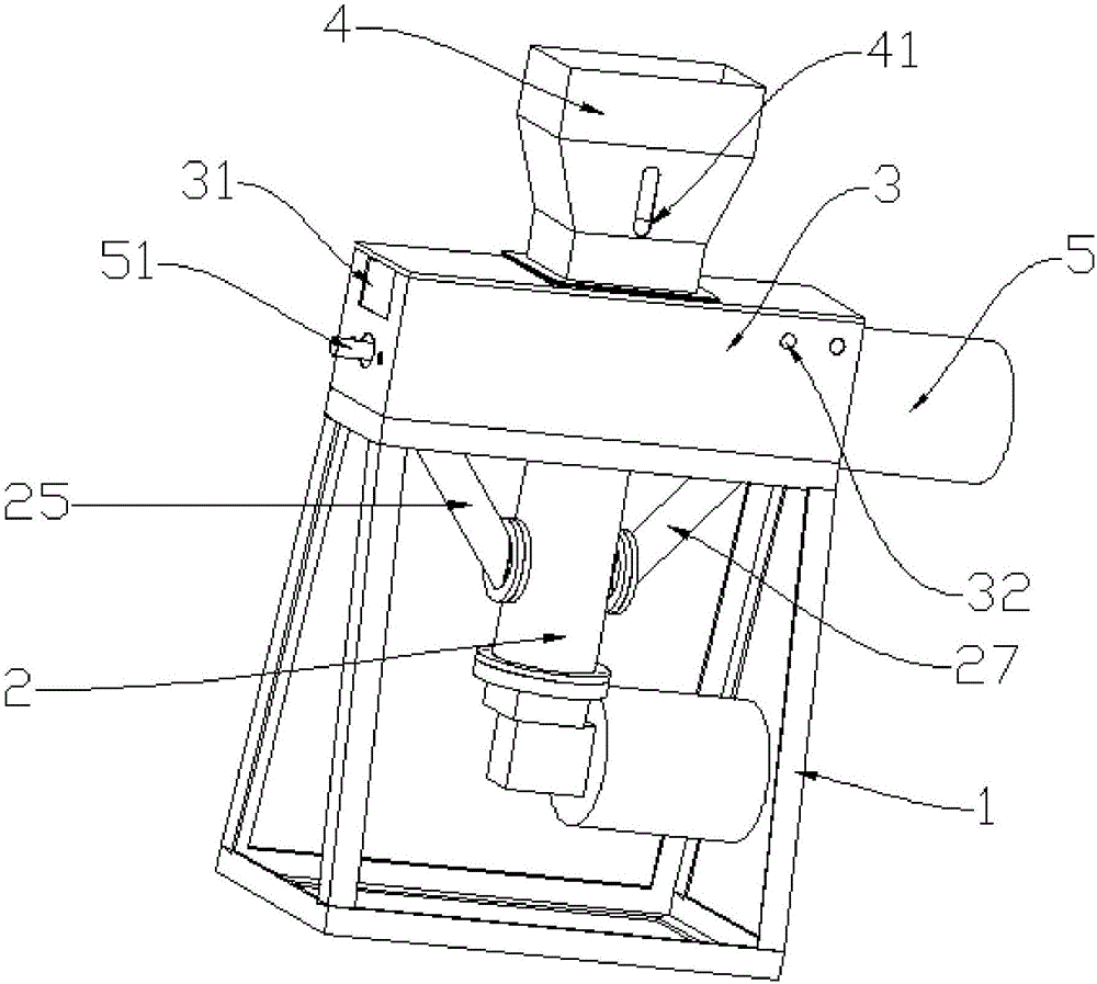
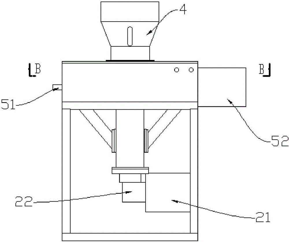
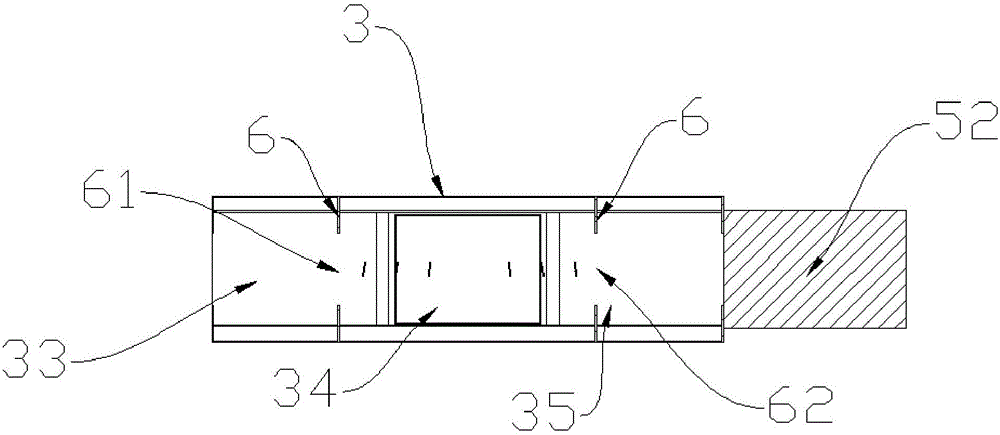
The invention provides a powder spraying mechanism, and belongs to the field of processing equipment for fabrication processing of parts. The powder spraying mechanism comprises a support frame, a box body, a lower ash raising assembly, an upper ash raising assembly and a hopper; the upper ash raising assembly comprises a rotating rod and a first motor for driving the rotating rod to rotate; the rotating rod comprises a middle part and end parts which are arranged symmetrically relative to the middle part; a first spiral piece is fixedly arranged on the outer ring of the middle part; a first motor is arranged outside the box body and is fixedly connected with the end parts; the box body is successively divided into a first hollow chamber, a second hollow chamber and a third hollow chamber by partition plates; the first hollow chamber and the third hollow chamber are arranged symmetrically relative to the second hollow chamber; the middle part is arranged in the second hollow chamber; end surfaces are arranged in the first hollow chamber and the third hollow chamber; a first notch is formed in the upper end of the partition plate between the first hollow chamber and the second hollow chamber; and a second notch is formed in the upper end of the partition plate between the second hollow chamber and the third hollow chamber. The powder spraying mechanism disclosed by the invention can spray powder on two workpieces at the same time, so that the working efficiency is greatly enhanced and the labor intensity is reduced.

Description

technical field [0001] The invention belongs to the field of parts processing equipment, in particular to a powder spraying mechanism. Background technique [0002] After the machining of mechanical parts, in order to improve the product performance of the parts or facilitate storage and transportation, it is often necessary to carry out subsequent process treatments on the parts, such as nitriding or nitriding treatment, to improve the wear resistance of the parts surface, and to spray anti-rust layers Or smear butter, etc., to achieve anti-corrosion and oxidation, to facilitate the storage and transportation of parts, to ensure that the processed surface is oxidized or corroded during storage, which affects the product performance of parts, and the processing level of post-processing directly affects the use or assembly of parts. The quality and precision of the links are therefore very important. At present, in terms of parts processing, the most common anti-corrosion and...

Claims


Application Information

Patent Timeline
Patent Type & Authority Applications(China)
IPC IPC(8): B05C19/04B05C19/06B05C9/04
CPCB05C19/04B05C9/04B05C19/06
Inventor 何永彬
Owner 天津市瑞森金属制品有限公司
Why Eureka
Try Eureka