Punch die fast replacing device

A stamping die and fast technology, applied in the direction of forming tools, manufacturing tools, metal processing equipment, etc., can solve the problems of plastic deformation, time-consuming and labor-intensive, and reduced precision of sheet metal parts, so as to reduce rebound performance, improve precision, and improve The effect of stability

Active Publication Date: 2017-05-31
DOOR IND CO LTD CHONGQING DTOMO
View PDF8 Cites 12 Cited by
  • Summary
  • Abstract
  • Description
  • Claims
  • Application Information

AI Technical Summary

Problems solved by technology

[0003] In the process of sheet metal parts processing, the bending machine mold is mainly placed on the punching machine, and then the metal sheet is placed on the bending mold to bend the metal sheet. During the bending process, the gap between the upper and lower dies The force is applied to the sheet metal to cause plastic deformation of the sheet metal. During processing, different upper and lower dies should be selected according to the shape of the sheet metal. When the sheet metal is more complicated, the shape of the bend is also relatively Complicated, at this time, it is necessary to frequently replace the upper mold and the lower mold, and the replacement process is time-consuming and laborious; and during the processing, the workpiece will generate heat after plastic deformation, so let go of the workpiece at this time, and the workpiece The rebound performance is the strongest, which will reduce the precision of the finished sheet metal parts

Method used


Image

  • Punch die fast replacing device
  • Punch die fast replacing device

Examples


Embodiment Construction

[0021] The present invention will be described in further detail below by means of specific embodiments:

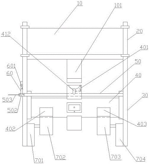
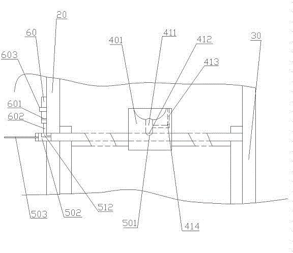
[0022] The reference signs in the drawings of the description include: hydraulic table 10, upper mold 101, frame 20, machine table 30, rotating shaft 40, lower mold 401, first through hole 411, first seal 412, return hole 413, electromagnetic Valve 414, first transmission tooth 402, second transmission tooth 403, limit rod 50, second through hole 501, slider 502, third through hole 512, slider 503, second seal 504, alcohol tube 60, A liquid level sensor 601 , a water pipe 602 , a fixed frame 603 , a first motor 701 , a first driving gear 702 , a second motor 703 , and a second driving gear 704 .

[0023] The embodiment is basically as attached figure 1 And attached figure 2 Shown: a stamping die quick replacement device, including a hydraulic table 10 and a frame 20 . The hydraulic platform 10 is arranged on the upper end of the frame 20, and the hydraulic platform 10...


PUM


Abstract

The invention relates to the field of machining and particularly discloses a punch die fast replacing device. The punch die fast replacing device comprises a hydraulic table and a rack. The hydraulic table is arranged at the upper end of the rack and is vertically and slidably connected with the rack; the lower surface of the hydraulic table is parallel to the horizontal plane; a machine table is fixedly mounted at the lower end of the rack; an upper die is detachably mounted on the lower surface of the hydraulic table; a rotary shaft rotationally connected with the machine table is horizontally arranged on the machine table; a plurality of different types of lower dies are mounted on the rotary shaft circumferentially; the upper die faces the rotary shaft; and the axes of the lower dies are perpendicular t to the axis of the rotary shaft. The punch die fast replacing device further comprises a first motor and a first driving gear which are both arranged at the lower end of the rack; the first driving gear is fixedly connected with the power output end of the first motor; and first transmission teeth engaged with the first driving gear are disposed at the end, close to the rack, of the rotary shaft. By means of the scheme, fast replacement of the lower dies can be achieved.

Description

technical field [0001] The invention belongs to the field of mechanical processing, and in particular relates to a stamping device for metal plate parts. Background technique [0002] Sheet metal parts have the characteristics of light weight, high strength, low cost, and good mass production performance, and have been widely used in electronic appliances, communications, automobile industry, medical equipment and other fields. Especially in computer cases, mobile phones, and MP3 players, plate-like metal is an essential component. As the application of sheet metal parts becomes more and more extensive, the demand for sheet metal parts is also increasing, and the requirements for processing accuracy are also getting higher and higher. [0003] In the process of sheet metal parts processing, the bending machine mold is mainly placed on the punching machine, and then the metal sheet is placed on the bending mold to bend the metal sheet. During the bending process, the gap bet...

Claims


Application Information

Patent Timeline
IPC IPC(8): B21D37/14
CPCB21D37/14
Inventor 万贤平
Owner DOOR IND CO LTD CHONGQING DTOMO
Why Eureka
Try Eureka