
Device and method capable of conducting whole-process capping and decapping on steel ladle

A technology of adding cover and ladle, which is applied in the direction of metal processing equipment, casting molten material container, casting equipment, etc., can solve the troubles of design technicians and steel factory technicians, high requirements on the space size of the production site, and gear-shaped structure Problems such as equipment production stoppage, to achieve the effect of good promotion and use value, compact structure, and elimination of safety hazards

Inactive Publication Date: 2017-05-31
宣化钢铁集团有限责任公司
View PDF5 Cites 7 Cited by
  • Summary
  • Abstract
  • Description
  • Claims
  • Application Information

AI Technical Summary

Problems solved by technology

[0003] At present, the ladle uncovering and capping equipment in many steel mills is a gear-shaped structure. This structure has high requirements on the space size of the production site, and it is impossible to realize the whole process of capping in the true sense. In addition, once the gear-shaped structure equipment fails, it will Immediate production stoppage accident
This problem has not been effectively solved so far, and it has become a difficult problem that has plagued design technicians and steel mill technicians for a long time, and it needs to be solved urgently

Method used


Image

  • Device and method capable of conducting whole-process capping and decapping on steel ladle
  • Device and method capable of conducting whole-process capping and decapping on steel ladle
  • Device and method capable of conducting whole-process capping and decapping on steel ladle

Examples


Embodiment Construction

[0023] The invention provides a device and method for uncapping a steel ladle. Using the device and method, the ladle can be smoothly uncapped during transportation, thereby reducing the temperature drop of the molten steel process and lowering the tapping temperature of the converter.

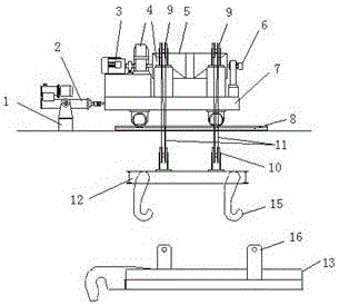
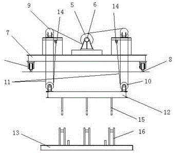
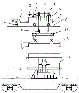
[0024] The ladle adding and uncovering device of the present invention consists of a bracket 1, an electro-hydraulic push rod 2, a motor 3, a reducer 4, a reel 5, a limiter 6, a moving trolley 7, a track 8, a fixed pulley block 9, a movable pulley block 10, and a steel wire rope. 11, hanger 12, wire rope fixing point 14, suspension hook 15 are formed.

[0025] figure 1 , 2 It shows that the lower end of the bracket 1 is welded and fixed to the embedded plate on the upper platform of the workshop, the body of the electro-hydraulic push rod 2 is connected with the bracket 1, and the front joint of the electro-hydraulic push rod 2 is connected with the mobile trolley 7.

[0026] figure 1 , 2 ...


PUM


Abstract

The invention discloses a device and method capable of conducting whole-process capping and decapping on a steel ladle and belongs to steel ladle capping and decapping equipment and method. The device and method capable of conducting whole-process capping and decapping on the steel ladle are used for conducting capping and decapping operation on the steel ladle. According to the technical scheme, a body of an electric-hydraulic push rod is connected with a support; the front portion of the electric-hydraulic push rod is connected with a moving trolley; a rail is mounted on a platform on the upper portion of a workshop; the moving trolley is located on the rail; a winding device is mounted on the moving trolley; the lower portion of the winding device is connected with a cap hoisting; and the cap hoisting is detachably connected with a cap. By means of the moving trolley, the rail and the electric-hydraulic push rod of the device, the cover hoisting can be moved to the hoisting position of the cap; by means of the winding device, the cap hoisting tool is ascended and descended; and the tasks of mounting and removing the cap are completed. The steel ladle capping and decapping device is compact in structure, small in occupied space, steady and reliably in operation and particularly applicable to rebuilding and upgrading of a steel mill; and after rebuilding, the original technological arrangement structure is not affected. The steel ladle capping and decapping method is convenient and fast to use, operation time is saved, and potential safety hazards are eliminated.

Description

technical field [0001] The invention relates to a device and method for taking up less space and enabling ladles to be uncapped throughout the process, and belongs to the technical field of ladle uncapping equipment and methods. Background technique [0002] The temperature in the ladle running state directly affects the smelting process operation and the metallurgical quality of molten steel. Aiming at the problem of large fluctuations in molten steel temperature during the steelmaking process, measures such as strengthening ladle baking, improving ladle heat turnover, optimizing the ladle lining structure, adding heat insulating agent during molten steel operation, and covering the ladle during pouring are generally adopted to reduce the cooling of molten steel. . In the above methods, the role of ladle capping is obvious. Research shows that after a 150t ladle is empty, the radiation heat loss from the lining to the air in the first 20 minutes will cause the temperature ...

Claims


Application Information

Patent Timeline
IPC IPC(8): B22D41/00
CPCB22D41/00
Inventor 刘志军闫卫兵吕岩杨朝辉刘海邢万里任毅张洁郭旭东
Owner 宣化钢铁集团有限责任公司
Learn More