Connecting device for material belts

A technology for connecting equipment and strips, applied in welding equipment, metal processing equipment, welding positions, etc., can solve the problems of reducing the production efficiency of cutting and feeding machines, increasing the failure of cutting and feeding machines, and increasing the production cost of enterprises. Achieve the effect of avoiding waste, reducing failure rate and improving production efficiency

Active Publication Date: 2017-05-31
GEER TECH CO LTD
View PDF8 Cites 3 Cited by
  • Summary
  • Abstract
  • Description
  • Claims
  • Application Information

AI Technical Summary

Problems solved by technology

[0003] However, in the current production process, when a plate of steel sheet material is cut, it needs to be stopped and replaced manually. Therefore, the cutting and feeding machine needs to be stopped and started frequently, which not only increases the failure rate of the cutting and feeding machine risk, and also reduces the production efficiency of the cutting and feeding machine; at the same time, due to the limitation of the cutting machine’s feeding mechanism, too short material belts cannot be used, resulting in a section of material belt left at both ends of each material belt, which is not It can be cut into inserts for injection molding products, forming waste, causing serious waste, and correspondingly increasing the production cost of the enterprise

Method used


Image

  • Connecting device for material belts
  • Connecting device for material belts
  • Connecting device for material belts

Examples


Embodiment 1

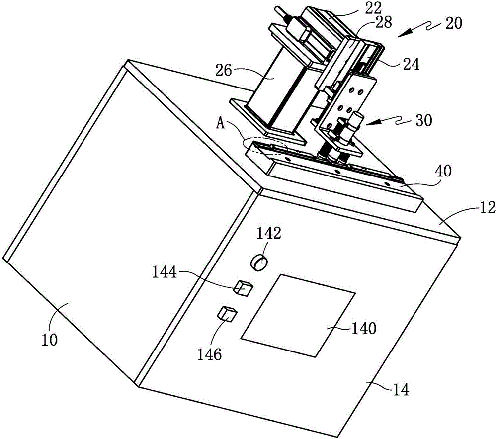
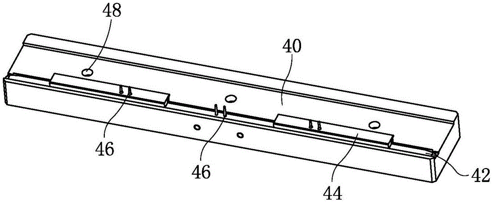
[0037] Such as figure 1As shown, a strip connecting device includes an operation platform 12, a support base 26 is arranged on the operation platform 12, and a moving mechanism 20 is installed on the support base 26. The moving mechanism 20 comprises a vertically moving mechanism 22 installed longitudinally on the top of the supporting seat 26, and the end of the force-bearing part of the longitudinally moving mechanism 22 is vertically fixed with a mounting plate 28, and a vertically moving mechanism 24 is vertically installed on the mounting plate 28. A welding device 30 is installed on the stressed part of the vertical moving mechanism 24, and the welding device 30 includes a vertically arranged soldering iron 34 (see FIG. 3 ). A strip positioning plate 40 is arranged laterally on the operating platform 12 in front of the support base 26 . In this embodiment, it is preferred that the longitudinal moving mechanism 22 is an electric cylinder, and the longitudinal moving mech...

Embodiment 2

[0049] This embodiment is basically the same as Embodiment 1, the difference is that:

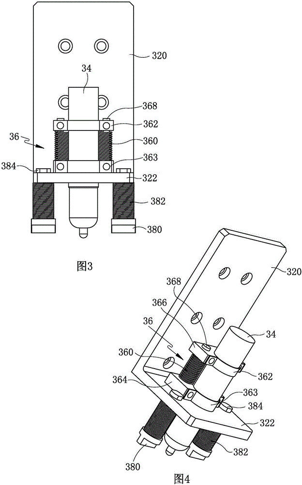
[0050] As shown in Figure 5, the structure of the height adjustment assembly 36 is different from that in Embodiment 1. In this embodiment, the height adjustment assembly 36 also includes two vertically telescopic adjustment springs 360, both of which are compression springs. The lower ends of the springs 360 are all fixed on the upper side of the bottom plate 322, and an adjustment positioning plate 366 is fixed on the upper end at the same time. The structure of the adjustment positioning plate 366 is consistent with that in Embodiment 1. Soldering iron 34 on.

[0051] As shown in Figure 5, the inside of two adjustment springs 360 is respectively provided with a first guide column 368, and the first guide column 368 is a threaded column, and the lower end of the first guide column 368 is fixed on the base plate 322, and the upper end of the first guide column 368 Through the adjustment a...


PUM


Abstract

The invention discloses a connecting device for material belts, and relates to the technical field of processing equipment of injection molding inserts. The connecting device comprises moving mechanisms, a welding device and a material belt locating plate, wherein the moving mechanisms comprise a longitudinal moving mechanism and a vertical moving mechanism; the vertical moving mechanism is mounted on a stress part of the longitudinal moving mechanism; the welding device is mounted on a stress part of the vertical moving mechanism; the welding device comprises vertically arranged soldering iron; and a plurality of locating pins matched with locating holes in the material belts are formed in the material belt locating plate. According to the connecting device for the material belts, the technical problems that in the prior art, the material belt processing efficiency is low and lots of waste materials are generated are solved, connectors of two rolls of material belts or small sections of material belts can be connected, the stopping time of a cutting feeding machine is decreased, the production efficiency of the cutting feeding machine is improved, waste of the material belts is avoided as well, and the production cost of enterprises is reduced.

Description

technical field [0001] The invention relates to the technical field of injection molding insert processing equipment, in particular to a connection device for connecting injection molding insert strips. Background technique [0002] The injection molding process refers to the process of making molten raw materials into products of a certain shape through operations such as pressurization, injection, cooling, and detachment. The injection molding process is widely used in various industries, including the electroacoustic industry. In the injection molding production of products, many products are injected with inserts, such as steel sheets. In order to realize automatic production by placing the steel sheet into the injection mold, a fully automatic steel sheet cutting and feeding machine is generally used at present to cut the disc-shaped steel sheet material into individual inserts, and then cooperate with the manipulator to cut the The cut inserts are placed into injectio...

Claims


Application Information

Patent Timeline
Patent Type & Authority Applications(China)
IPC IPC(8): B23K3/00B23K3/02B23K3/08B23K103/04B23K101/16
CPCB23K3/00B23K3/026B23K3/087B23K2101/16B23K2103/04
Inventor 谢鹏魏宝林范金泉王进强张烨
Owner GEER TECH CO LTD
Why Eureka
Try Eureka