Automatic steel bar lap joint and welding device

A technology for welding devices and steel bars, which is applied in the direction of auxiliary devices, welding equipment, welding equipment, etc., to achieve the effects of convenient operation, fast welding speed and high efficiency

Pending Publication Date: 2017-05-31
NO 3 ENG LIMITED OF CR20G
View PDF0 Cites 4 Cited by
  • Summary
  • Abstract
  • Description
  • Claims
  • Application Information

AI Technical Summary

Problems solved by technology

[0003] The purpose of the present invention is to overcome the defects of manual welding by manual operation at present, and disclose an automatic lap welding device for steel bars

Method used


Image

  • Automatic steel bar lap joint and welding device
  • Automatic steel bar lap joint and welding device

Examples


Embodiment Construction

[0010] Below in conjunction with embodiment and accompanying drawing, the present invention is described in further detail:

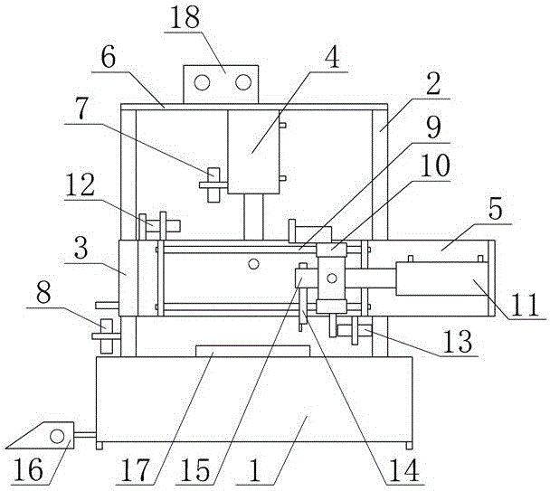
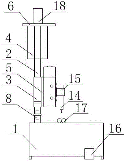
[0011] Two lifting sliding columns 2 are fixed on the base 1, and a lifting sliding sleeve 3 is set outside the lifting sliding columns 2. The upper ends of the lifting sliding columns 2 are connected with a fixing plate 6, and a power distribution box 18 is arranged on the fixing plate 6. Using the connecting plate 5 Connect the two lifting sliding sleeves 3 to each other and extend to the right side, respectively fix the traverse slide bar 9 on the upper and lower sides of the connecting plate 5, and install the left limit switch 12 on the connecting plate 5 on the left upper part of the traverse slide bar 9, Right limit switch 13 is installed on the connecting plate 5 of traversing slide bar 9 right bottoms, the fixed end of lift cylinder 4 is fixed below the center of fixed plate 6, upper limit switch 7 is installed on the left side of lift cylinder ...


PUM


Abstract

The invention discloses an automatic steel bar lap joint and welding device. Lifting sliding columns and lifting sliding sleeves are fixed to a base. The lifting sliding sleeves are mutually connected through a connecting plate and extend rightwards. Transverse moving sliding rods are vertically fixed to the connecting plate, a left limiting switch is arranged at the upper left portion of the connecting plate, and a right limiting switch is arranged at the right lower portion of the connecting plate. A lifting air cylinder and an upper limiting switch are fixed to the lower face of a fixing plate. A lower limiting switch is arranged on the outer side of the left lifting sliding column. The telescopic end of the lifting air cylinder is hinged to the center of the connecting plate. The extending end of the connecting plate is fixed to the fixing end of a transverse moving air cylinder. The telescopic end of the transverse moving air cylinder is hinged to the middles of transverse moving sliding sleeves. The transverse moving sliding rods are arranged in sliding openings of the transverse moving sliding sleeves correspondingly. A welding gun is arranged on the side face of one transverse moving sliding sleeve. The automatic steel bar lap joint and welding device overcomes the defects existing in the process of manual lap joint and welding operation of steel bars, and professional technique welders are not needed; and operation is simple, convenient and fast, the welding speed is high, efficiency is high, welding lines are full, uniform and attractive, and automation of the electric welding technology is achieved.

Description

technical field [0001] The invention relates to a welding device, in particular to a steel bar automatic lap welding device, which belongs to the field of building construction. Background technique [0002] With the rapid development of new technologies, various large-scale construction projects continue to emerge, and the speed and mileage of high-speed trains continue to set new records. These large-scale construction projects require the use of a large number of steel bars, which must be lap-welded according to construction specifications , so that the steel bars continue to be firmly connected as a whole, thereby ensuring the quality of the project. Therefore, lap welding is the most common steel bar processing technology in large-scale construction projects. In order to achieve the purpose of firmly welding the steel bars, it is necessary to ensure that the welds between the steel bars are full, smooth and even. At present, steel bar welding is performed by manual op...

Claims


Application Information

Patent Timeline
Patent Type & Authority Applications(China)
IPC IPC(8): B23K28/00B23K37/00B23K101/32
CPCB23K37/00B23K28/00B23K2101/32
Inventor 马小利冯建军李福成王武高周明升王志贵曾小东周峰刘波
Owner NO 3 ENG LIMITED OF CR20G
Why Eureka
Try Eureka