Electric Bench Vise

A bench vise and electric technology, applied in the field of bench vises, can solve the problems of high labor intensity, slow speed, and low work efficiency, and achieve the effect of reducing labor intensity, high efficiency, and fewer originals

Active Publication Date: 2018-04-24
苗木美
View PDF12 Cites 0 Cited by
  • Summary
  • Abstract
  • Description
  • Claims
  • Application Information

AI Technical Summary

Problems solved by technology

[0002] Bench vise is a general-purpose tool installed on the workbench for clamping and stabilizing the workpiece. It is an essential tool for mechanical production and mechanical maintenance. At present, the known bench vise is to use manpower to pull the handle to drive the screw Rotate and push the nut on the movable jaw to make the movable jaw approach the fixed pliers to clamp the workpiece. It takes a lot of force when the handle is pulled by manpower, the labor intensity is high, the speed is slow, and the work efficiency is low. Therefore, people hope to have a A kind of very labor-saving, fast bench vise replaces known bench vise

Method used


Image

  • Electric Bench Vise
  • Electric Bench Vise
  • Electric Bench Vise

Examples


Embodiment Construction

[0018] The specific implementation manner of the present invention will be further described below in conjunction with the accompanying drawings.

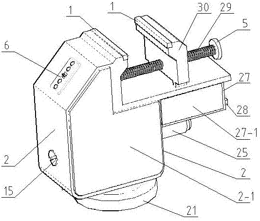
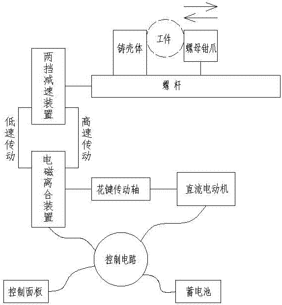
[0019] According to the present invention figure 1 , figure 2 Shown; The present invention is to drive the spline drive shaft → transmission → electromagnetic clutch device → transmission → two-speed deceleration device → transmission → screw to rotate to make the nut claw move by accumulator to DC motor power supply; control circuit and accumulator, DC motor, electromagnetic The clutch device and the control panel are connected by wires; the operation control panel can realize the left and right movement of the nut claws, and can perform the clamping or loosening function on the workpiece.

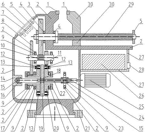
[0020] The structural sectional view of embodiment 1 of the present invention: in image 3 Middle; the DC motor (25) is fixedly installed on the cast housing (2), connected with the short spline shaft (24), and the short spline shaft (24) a...


PUM


Abstract

The invention discloses an electric bench screw. The electric bench screw does not need to be pulled manually, works electrically, is controlled through a circuit and is operated through buttons, application is convenient and rapid, and the working efficiency is high. According to the technical scheme, firstly, a storage battery is used as a power source, and power is provided by a direct-current motor; secondly, an electromagnetic clutch device is arranged and used for transmitting the power of the direct-current motor to a screw for rotation; thirdly, a high-gear reducing transmission device and a low-gear reducing transmission device are arranged, and speed adjustment is facilitated; and fourthly, a control panel and the control circuit are arranged and used for controlling the direct-current motor and the electromagnetic clutch device. The electric bench screw has the beneficial effects that the workpiece clamping speed is high, the efficiency is high, manpower is saved, work fatigue of operators is relieved, and the working efficiency and production benefits of bench worker of all walks of life can be improved.

Description

technical field [0001] The invention relates to a bench vise, in particular to an electric bench vise. Background technique [0002] Bench vise is a general-purpose tool installed on a workbench for clamping and stably processing workpieces. It is an essential tool for mechanical production and mechanical maintenance. Rotate and push the nut on the movable jaw to make the movable claws approach the fixed pliers to clamp the workpiece. It takes a lot of force when the handle is pulled by manpower, the labor intensity is high, the speed is slow, and the work efficiency is low. Therefore, people hope to have a A kind of very labor-saving, fast bench vise replaces known bench vise. Contents of the invention [0003] In order to overcome the defects and deficiencies of the known bench vise in the above background technology, the present invention provides an electric bench vise, which does not need manpower to pull, electric work, circuit control, button operation, easy to use...

Claims


Application Information

Patent Timeline
Patent Type & Authority Patents(China)
IPC IPC(8): B25B1/18B25B1/02
CPCB25B1/02B25B1/18
Inventor 苗木美
Owner 苗木美
Why Eureka
Try Eureka