
Detaching device

A technology of dismantling device and driving device, which is applied to hand-held tools, manufacturing tools, etc., can solve the problems of easy fatigue of workers and strong manual labor, and achieve the effect of reducing labor intensity.

Inactive Publication Date: 2017-05-31
SHENZHEN TINNO WIRELESS TECH
View PDF6 Cites 6 Cited by
  • Summary
  • Abstract
  • Description
  • Claims
  • Application Information

AI Technical Summary

Problems solved by technology

Manual separation of the cover and the touch screen causes the staff to be easily fatigued, and the manual labor is strong

Method used


Image

  • Detaching device
  • Detaching device
  • Detaching device

Examples


Embodiment Construction

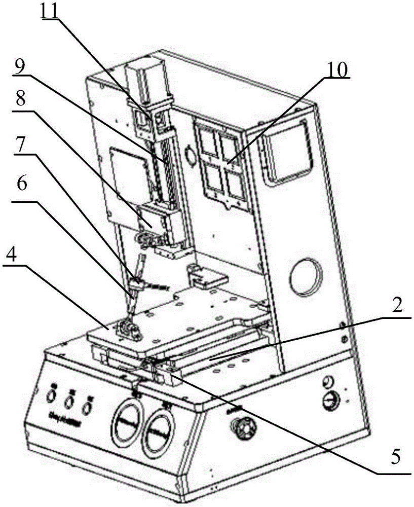
[0026] The invention discloses a dismantling device to reduce the manual labor intensity of separating the face shell from the touch screen.

[0027] The following will clearly and completely describe the technical solutions in the embodiments of the present invention with reference to the accompanying drawings in the embodiments of the present invention. Obviously, the described embodiments are only some, not all, embodiments of the present invention. Based on the embodiments of the present invention, all other embodiments obtained by persons of ordinary skill in the art without making creative efforts belong to the protection scope of the present invention.

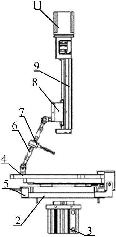
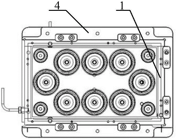
[0028] see Figure 1-Figure 3 , figure 1 Schematic diagram of the structure of the disassembly device provided by the embodiment of the present invention; figure 2 The left view of the disassembly device provided by the embodiment of the present invention; image 3 It is a schematic structural diagram of the second ...


PUM


Abstract

The invention discloses a detaching device comprising a fixture, a first suction plate and a second suction plate. After glue between a face shell and a touch screen is softened and loses efficacy, the first suction plate makes contact with the face shell under the effect of a first driving device, a vacuum pump conducts vacuum pumping operation on a first suction disc of the first suction plate, and suction of the face shell through the first suction plate is achieved. The second suction plate makes contact with the touch screen under the effect of a second driving device, the vacuum pump conducts vacuum pumping operation on a second suction disc of the second suction plate, and suction of the touch screen through the second suction plate is achieved. A second driving device drives the second suction plate to move towards the direction enabling the touch screen and the face shell to be separated, so that the face shell and the touch screen are separated. According to the scheme, separating of the face shell and the touch screen is achieved though the detaching device, accordingly compared with a mode of separating through manual operation in the prior art, manual labor intensity is reduced effectively.

Description

technical field [0001] The invention relates to the technical field of electronic products, in particular to a disassembly device. Background technique [0002] The face shell is a plastic part that fixes the touch screen on the front of the electronic product, and can also play the role of installing the mobile phone. The cover is fixedly connected to the touch screen, and the cover needs to be separated from the touch screen during maintenance. The traditional disassembly method is to put the cover and the touch screen on the heating plate, so that the glue used to fix the cover and the touch screen is softened and invalidated, and then manually separate the cover and the touch screen with a suction cup. Manual separation of the face shell and the touch screen causes the staff to be easily fatigued, and the manual labor is strong. [0003] Therefore, how to reduce the manual labor intensity of separating the cover from the touch screen has become a technical problem to b...

Claims


Application Information

Patent Timeline
Patent Type & Authority Applications(China)
IPC IPC(8): B25B27/00
CPCB25B27/00
Inventor 冯国庆张北林余意
Owner SHENZHEN TINNO WIRELESS TECH
Learn More