
A hybrid electric vehicle power system

A hybrid electric vehicle and power system technology, applied in the field of hybrid electric vehicle power system, can solve problems such as difficult switching, large continuous speed regulation, and large impact of the power system

Active Publication Date: 2020-10-02
CHONGQING TSINGSHAN IND
View PDF7 Cites 0 Cited by
  • Summary
  • Abstract
  • Description
  • Claims
  • Application Information

AI Technical Summary

Problems solved by technology

For this reason, the common hybrid electric vehicle power system in the market, the engine and the drive motor are directly connected, the technical problem is; in the hybrid mode, it is necessary to ensure that the speed of the engine and the drive motor are consistent at the same time to achieve better power output , the power matching is poor, and the large torque and continuous speed regulation of the drive motor cannot be fully utilized; in the hybrid mode, the transmission ratio changes discontinuously, and there is a shift shock, making it difficult to make the engine work in the high-efficiency zone. The smoothness of gears is poor and the work efficiency is not high; at the same time, the engine and the drive motor are directly connected. When switching between the three power modes of single engine, pure electric and hybrid power, it will have a great impact on the power system, and it is often difficult to smoothly switch

Method used


Image

  • A hybrid electric vehicle power system

Examples


Embodiment Construction

[0010] Preferred embodiments of the present invention will be described in detail below in conjunction with the accompanying drawings.

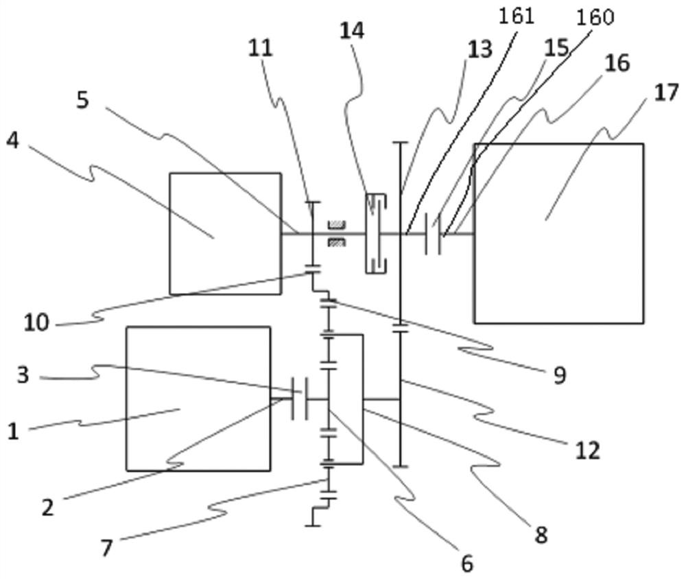
[0011] see figure 1 , the power system of the hybrid electric vehicle of the present invention comprises an engine 1 and a crankshaft 2 connected to the right end of the engine 1, a first clutch 3, a drive motor 4 and a motor shaft 5 stretched out from the right end of the drive motor 4, the second Two clutches 15, a main shaft 16 and a transmission 17. Depend on figure 1 It can be seen that the present invention also includes an outer ring gear 10, a motor gear 11, a first gear 12, a second gear 13, a lock-up clutch 14, and a planetary row including a sun gear 6, a planetary gear 7, a planet carrier 8, and a ring gear 9, The crankshaft 2 of the engine 1, the first clutch 3, the sun gear 6 of the planetary row and the first gear 12 are sequentially connected from left to right, and the main shaft 16 includes a first main shaft 160 and a sec...


PUM


Abstract

The invention provides a power system of a hybrid power vehicle. The power system is excellent in power matching property, a crank shaft, a first clutch, sun wheels and a first gear are connected in sequence from left to right, a first main shaft and a second main shaft are coaxial with a motor shaft of a driving motor, the first main shaft stretches out of the left end of a transmission towards the left, the left end of the first main shaft is connected with the right end of a second clutch, the right end of the second main shaft is connected with the left end of the second clutch, the left end of the second main shaft is connected with the right end of a locking clutch, the left end of the locking clutch is connected with the motor shaft of the driving motor, a motor gear is installed on the motor shaft of the driving motor and located on the left side of the locking clutch, a second gear is installed on the second main shaft and located between the locking clutch and the second clutch, the motor gear and the second gear are meshed with an outer gear ring and the first gear respectively, the outer gear ring and the first gear are fixedly connected with gear rings of planet rows and a planet carrier respectively, the sun wheels are located in the planet carrier, planet wheels are rotatably installed on the planet carrier, and the gear rings are arranged outside the planet carrier.

Description

technical field [0001] The invention relates to a hybrid electric vehicle, in particular to a hybrid electric vehicle power system. Background technique [0002] The power system of a hybrid electric vehicle should usually have functions such as power mode switching, matching of the engine and the drive motor, etc. For this reason, the common hybrid electric vehicle power system in the market, the engine and the drive motor are directly connected, the technical problem is; in the hybrid mode, it is necessary to ensure that the speed of the engine and the drive motor are consistent at the same time to achieve better power output , the power matching is poor, and the large torque and continuous speed regulation of the drive motor cannot be fully utilized; in the hybrid mode, the transmission ratio changes discontinuously, and there is a shift shock, making it difficult to make the engine work in the high-efficiency zone. The smoothness of gears is poor and the work efficiency...

Claims


Application Information

Patent Timeline
IPC IPC(8): B60K6/365B60K6/44
CPCB60K6/365B60K6/44Y02T10/62
Inventor 毛江刘巍胡芳刘拴起庄周樵明月张代明吴金兵黄刚强
Owner CHONGQING TSINGSHAN IND
Learn More