Driver signal analysis method for electric drive track vehicle control

A technology of analysis method and control method, which is applied in the field of electric drive crawler vehicle control, can solve the problems of difficult balance between system power supply and power consumption, unknown drive motor power, and uncontrolled drive motor output power, etc.

Active Publication Date: 2017-05-31
CHINA NORTH VEHICLE RES INST
View PDF5 Cites 23 Cited by
  • Summary
  • Abstract
  • Description
  • Claims
  • Application Information

AI Technical Summary

Problems solved by technology

[0003] However, if the accelerator pedal signal is directly corresponding to the vehicle speed control, the torque is not the target controlled quantity, so the output power of the drive motor will not be controlled, which brings the problem of difficult balance between system power supply and power consumption
Especially when the driver reduces or fully rel

Method used


Image

  • Driver signal analysis method for electric drive track vehicle control
  • Driver signal analysis method for electric drive track vehicle control
  • Driver signal analysis method for electric drive track vehicle control

Examples


Embodiment 1

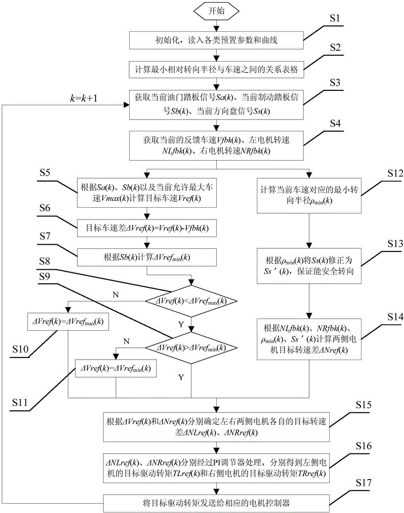
[0077] This embodiment is applicable to the situation where the motor control is in the torque mode, and the driver signal analysis method includes the following steps:

[0078] Described driver's signal analysis method comprises the steps:

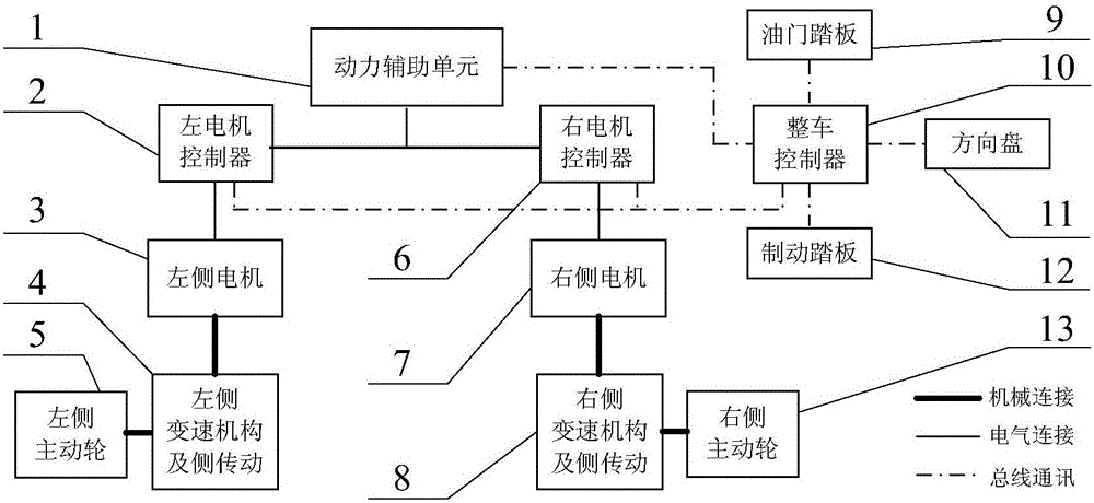
[0079] Step S1: The vehicle controller 10 initializes, and reads the parameters including road running resistance coefficient f, maximum steering resistance coefficient μ max , road surface adhesion coefficient Transmission ratio i b , side transmission ratio i c , vehicle center distance B, vehicle length L, vehicle weight m, driving wheel radius r, and read in the preset parameters of the vehicle including the maximum allowable vehicle speed Vmax and the maximum value of the increase rate ΔVref max In the preset control parameters, read in the discretization curve of the inherent steering safety factor δ changing with the vehicle speed V, and read in the inherent T-n characteristic curves of the motors on both sides; then go to step...

Embodiment 2

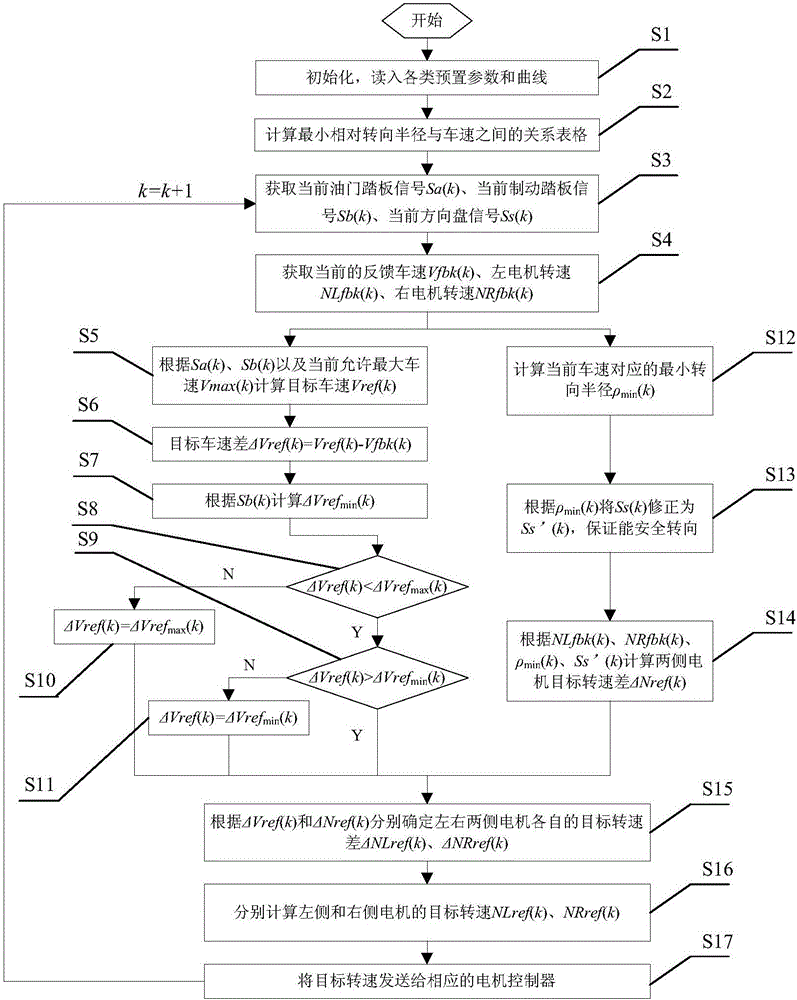
[0122] This embodiment is applicable to the case where the motor control is in the rotational speed mode, and the driver signal analysis method from step S1 to step S15 is the same as that in embodiment 1, the difference is that:

[0123] Step S16: According to the target speed difference ΔNLref(k) of the left motor, the target speed difference ΔNRref(k) of the right motor obtained in the previous step, the feedback speed NLfbk(k) of the left motor, and the feedback speed NRfbk of the right motor (k), respectively calculate the target speed NLref(k) of the left motor and the target speed NRref(k) of the right motor:

[0124]

[0125] Step S17: Send the target speeds of the motors on both sides to the corresponding motor controllers, and control the motors on both sides to output corresponding speeds, so that the vehicle can complete the direct driving or steering function. Jump to step S3 to perform real-time control within the k+1 control period.

[0126] In summary, the ...


PUM


Abstract

The invention belongs to the technical field of electric drive track vehicle control, and particularly relates to a driver signal analysis method for electric drive track vehicle control. According to the method, target vehicle speed is determined by utilizing difference between the opening degree of an accelerator pedal and the opening degree of a brake pedal, and acceleration and deceleration slope control is realized by limiting the difference value of the target vehicle speed and the actual vehicle speed; the difference of the target rotating speed of motors on double sides is determined by utilizing a steering wheel angle and sideslip limit turning radius, so that the difference between the target rotating speed and the actual rotating speed of each of the motors on double sides is determined; the driving torque of each of the motors on double sides is obtained by a PI regulator, so that the control method enables the vehicle to finish straight driving and turning functions and avoids sideslip caused by too small turning radius.

Description

technical field [0001] The invention belongs to the technical field of electric transmission crawler vehicle control, and in particular relates to a driver signal analysis method for electric transmission crawler vehicle control. Background technique [0002] Electric transmission is more and more widely used in tracked vehicles, and double-sided motor drive is one of the typical transmission forms. When the whole vehicle adopts the closed-loop control of vehicle speed and steering radius, the speed of the driving wheel of the tracked vehicle is directly controlled, and the vehicle’s motion state is relatively stable. Therefore, the closed-loop mode of vehicle speed and steering radius is a suitable control method. Correct parsing of intents. [0003] However, if the accelerator pedal signal is directly used to control the vehicle speed, its torque is not the target controlled quantity, so the output power of the drive motor will not be controlled, which brings the problem ...

Claims


Application Information

Patent Timeline
IPC IPC(8): B60L15/38B60L15/20B62D11/04
CPCB60L15/2036B60L15/38B62D11/04Y02T10/72
Inventor 李春明薛天扬盖江涛曾根徐岩韩政达帅志斌张欣
Owner CHINA NORTH VEHICLE RES INST
Why Eureka
Try Eureka