Replaceable laser and array thereof

A laser, replaceable technology, applied in lasers, laser parts, laser parts and other directions, can solve the problems of cumbersome use steps, complex laser structure, helpless and so on, to reduce difficulty, improve popularization rate, precise mechanical docking Effect

Active Publication Date: 2019-11-08
尚华
View PDF7 Cites 2 Cited by
  • Summary
  • Abstract
  • Description
  • Claims
  • Application Information

AI Technical Summary

Problems solved by technology

For photodynamic therapy, there are many types of photosensitizers and applicable diseases, and new photosensitizers are constantly being launched on the market. Ordinary medical staff who do not have laser knowledge often change lasers and laser wavelengths. Unsure of what to do or easy to make mistakes
[0004] Moreover, the structure of the laser is complex, the price is high, and the steps of use are cumbersome, especially the lasers used in the existing photodynamic therapy instruments are all semiconductor lasers, and the inside of the laser not only needs to be powered by an external power supply, but also needs to be adjusted for power, wavelength, etc. For the control of various parameters such as adjustment and pulse adjustment, there are many electrical external power supply devices and parameter control devices, which must rely on multiple external power connectors for communication. A little carelessness will cause connection errors, which makes medical staff and medical staff use medical lasers. In particular, there is a fear of replacement, which seriously hinders the popularization and promotion of laser therapy equipment in medical treatment.

Method used


Image

  • Replaceable laser and array thereof
  • Replaceable laser and array thereof
  • Replaceable laser and array thereof

Examples


Embodiment 1

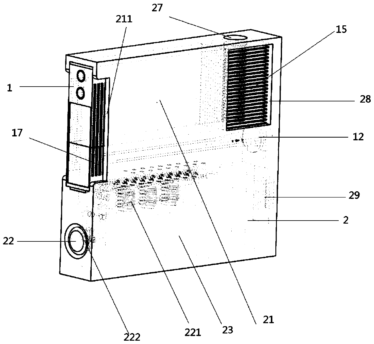
[0067] A replaceable laser such as Figure 1-10 As shown, it includes a casing 1 fixed with laser components and a casing 2 for clamping the casing 1; the casing 1 has a unique electrical interface 11 and several optical interfaces 12 docked with the casing 2; the The casing 1 can be extracted from the casing 2 and replaced with another casing containing laser components emitting lasers of different wavelengths.

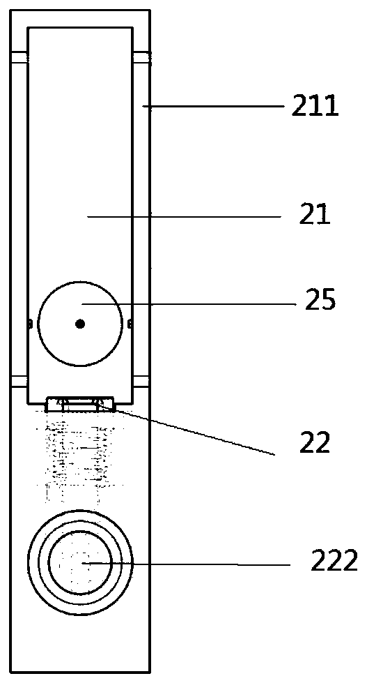
[0068] Specifically, the chassis 2 includes a first accommodating space 21 for accommodating the casing 1, a snap-in device 22, and a second accommodating space 23 for accommodating the snap-in device; the chassis 2 The front panel of the front panel is provided with an insertion port 211 for horizontally inserting the casing 1 into the first accommodating space 21, and the casing 1 is disassembled and replaced through the insertion port 211; the second accommodating space 23 is located in The space below the first accommodating space 21 communicates with the first ...

Embodiment 2

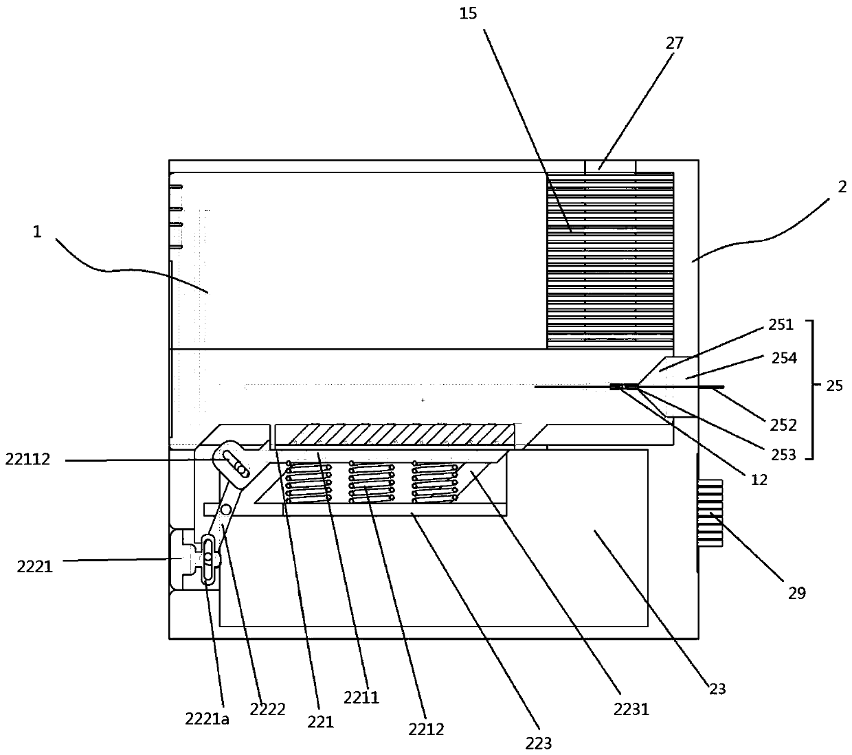
[0073] As a preference, the difference between this embodiment and the above-mentioned embodiments is that in order to realize the precise docking of the optical interface and the electrical interface between the casing 1 and the casing 2, the clamping device 22 is as Figure 6-8 As shown, it also includes a snap-in box 223, the snap-in box 223 is fixed in the second accommodating space 23, and the bottom of the elastic component 2212 is fixed at the bottom of the snap-in box 223, the buckle When the plywood 2211 moves up and down, it does not completely break away from the snap-in box 223; the left and right sides of the snap-in box 223 are provided with a number of inclined guide rails 2231 with the same inclination angle as the axis of the cylindrical protrusion 24, corresponding to the The left and right sides of the fastening plate 2211 are provided with inclined guide grooves 22111 . Or preferably, the left and right sides of the second accommodating space 23 are provide...

Embodiment 3

[0082] Preferably, the rear panel of the chassis 2 horizontally corresponding to the position of the insertion port 211 is provided with an optical connector 25 , and corresponding to the position of the optical connector 25 , the casing 1 is provided with a matching optical interface 11 . The inside of the optical interface 11 is connected with the laser output port in the casing 1 through an optical fiber. The different casings 1 have a unified optical interface 11 and electrical interface 12, which greatly reduces the difficulty for medical staff to switch laser wavelengths, and improves the popularization rate of laser therapy instruments in the medical field.

[0083] Specifically, as Figure 9 As shown, the optical interface 12 of the casing 1 includes a conical cavity 121 with a conical top at the front and an axis extending horizontally backward. A small cylindrical cavity 122 connected by conical cavities, the conical bottom part of the conical cavity 121 extends hor...


PUM


Abstract

The invention provides a replaceable laser and an array thereof. The replaceable laser is formed by casings, which are internally provided with laser elements and have uniform shapes and uniform electrical interfaces, and a case for clamping the casings. Power supply and parameter control of the laser elements are realized through cylindrical projections with tilt angle on the casings and a buckleplate and electrical interfaces in cylindrical through slots, and the cylindrical projections with tilt angle and the cylindrical through slots can realize precise positioning of the casings and thecase; and when the laser element in a different wavelength needs to be replaced, one only needs to pull the casing out of the case and replace the casing with another casing that contains a laser capable of emitting different-wavelength laser, thereby greatly reducing the difficulty of medical staffs in laser wavelength switching and improving popularization rate of laser treatment equipment in the medical field. According to the replaceable laser array, casings with different wavelength can be replaced in each case; and multiple cases can be connected with a variety of wavelength switching devices to achieve selective output of the wavelength.

Description

technical field [0001] The invention belongs to the field of laser medical equipment, and in particular relates to a replaceable laser and an array thereof for photodynamic therapy. Background technique [0002] Photodynamic therapy (Photodynamic Therapy, PDT) is a new technology that uses photodynamic effect for disease diagnosis and treatment. Its basis is the photodynamic effect. The photodynamic effect is a photosensitization reaction accompanied by biological effects involving oxygen molecules. The process is that the photosensitizer absorbed by the tissue is excited by the laser irradiation of a specific wavelength, and the photosensitizer in the excited state transfers energy to the surrounding oxygen to generate highly active singlet oxygen, and the singlet oxygen and adjacent biological Oxidation of macromolecules produces cytotoxicity, which in turn leads to cell damage and even death. Compared with traditional therapy, photodynamic therapy has the advantages of...

Claims


Application Information

Patent Timeline
Patent Type & Authority Applications(China)
IPC IPC(8): H01S3/02H01S5/022A61N5/067
CPCA61N5/062A61N2005/005A61N2005/063A61N2005/0632A61N2005/0664A61N5/067H01S3/02H01S5/022
Inventor 尚华
Owner 尚华
Why Eureka
Try Eureka