
Vehicular interceptor and high-pressure blow-molding rapid forming process thereof

A molding process and spoiler technology, which is applied in the direction of body, application, household components, etc., can solve the problems of easy damage or deformation, reduced rear wheel grip, and more steering of the car, so as to increase the compression resistance and bending resistance. capacity, improve installation efficiency, and prevent rainwater from gathering

Inactive Publication Date: 2017-05-31
江阴名旭模塑有限公司
View PDF7 Cites 5 Cited by
  • Summary
  • Abstract
  • Description
  • Claims
  • Application Information

AI Technical Summary

Problems solved by technology

[0002] The function of the car spoiler is mainly to reduce the lift at the rear of the vehicle. If the lift at the rear is greater than the lift at the front, it will easily lead to excessive steering, reduced rear wheel grip, and poor high-speed stability; lift is the same as wind resistance. It is proportional to the square of the speed of the vehicle, so cars with higher speeds, such as limousines and sports cars, are generally equipped with spoilers
[0003] The current spoiler has poor compression and bending resistance, is easy to be damaged or deformed, and the rear of the vehicle receives a high lift force, and cannot prevent rainwater from gathering. At the same time, the spoiler needs to be tightened during installation. More installation time, reducing installation efficiency
[0004] At the same time, the current spoiler needs to wait for it to cool slowly during blow molding, but it takes more time to complete the cooling molding process, which prolongs the molding time of the spoiler and reduces the blow molding efficiency

Method used


Image

  • Vehicular interceptor and high-pressure blow-molding rapid forming process thereof
  • Vehicular interceptor and high-pressure blow-molding rapid forming process thereof
  • Vehicular interceptor and high-pressure blow-molding rapid forming process thereof

Examples


Embodiment Construction

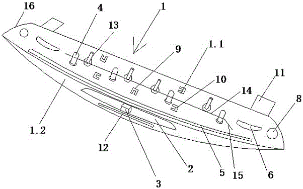
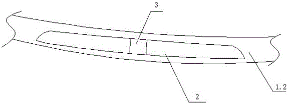
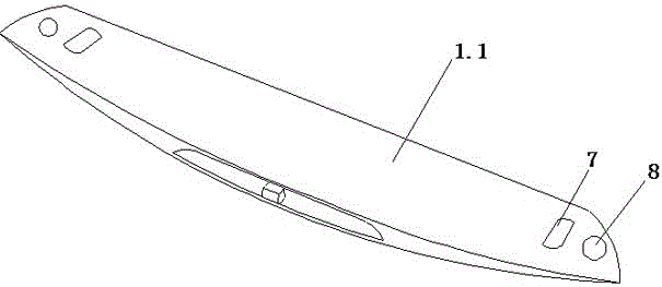
[0024] Such as Figure 1 to Figure 6 , the present invention relates to a spoiler for vehicles, comprising a spoiler body 1, a through hole 2 and a process piece 3, which improves the heat resistance of the spoiler, and the spoiler body 1 is composed of a bottom plate 1.1 and a vertical plate 1.2, the vertical plate 1.2 is provided with a through hole 2, and the through hole 2 is elongated. The process piece 3 is arranged in the through hole 2, and its two ends are connected and fixed with the vertical plate 1.2. The spoiler body 1 Bolts 4 are provided on the back of the spoiler, and the bolts 4 include a bolt seat 4.1, a bolt head 4.2 and a bolt protective sleeve 4.3. The bolt seat 4.1 is fixed on the back of the spoiler body 1, and the bolt head 4.2 is fixed on the bolt seat 4.1. On, the upper end of the bolt protective sleeve 4.3 is sealed, and the lower end is set on the bolt head 4.2;

[0025] The back of the spoiler body 1 is provided with a long inner concave rib 5 and...


PUM


Abstract

The invention relates to a vehicular interceptor and a high-pressure blow-molding rapid forming process thereof. A process slice is additionally arranged in a stripe-type through hole, and a supporting role is played on an interceptor body; a protective jacket is additionally arranged on each bolt to prevent the interceptor body from being collided during transportation to cause the bolts to be damaged or deformed; an inner concave rib is additionally arranged in the reverse side of the interceptor body, and rigidity of the interceptor body is improved; two lugs are arranged on the front side of the interceptor body, and lift force at the tail end of a vehicle can be reduced; drainage holes are formed in positions close to two sides of the interceptor body, and convergence of rainwater can be prevented; the bottom of each of a bolt mounting seat and buckle mounting seat of the interceptor body is relatively thin, pressure to the interceptor body is reduced, convex mark produced on the front side of the interceptor body is avoided, and attractiveness of the interceptor body is achieved; mounting of the interceptor body and the vehicle is facilitated by the aid of the interceptor body, and mounting efficiency of the interceptor body is improved; a lamp installation groove is arranged in the side edge of the interceptor body, other types of vehicles can be well alarmed, and safety in vehicle driving is further improved.

Description

technical field [0001] The invention relates to a vehicle spoiler and a high-pressure blow molding rapid forming process thereof, belonging to the technical field of automobile plastic parts. Background technique [0002] The function of the car spoiler is mainly to reduce the lift at the rear of the vehicle. If the lift at the rear is greater than the lift at the front, it will easily lead to excessive steering, reduced rear wheel grip, and poor high-speed stability; lift is the same as wind resistance. It is proportional to the square of the speed of the vehicle, so cars with higher speeds, such as limousines and sports cars, are generally equipped with spoilers. [0003] The current spoiler has poor compression and bending resistance, is easy to be damaged or deformed, and the rear of the vehicle receives a high lift force, and cannot prevent rainwater from gathering. At the same time, the spoiler needs to be tightened during installation. More installation time reduces ...

Claims


Application Information

Patent Timeline
Patent Type & Authority Applications(China)
IPC IPC(8): B62D35/00B29C49/04B29L31/30
CPCB62D35/007B29C49/04B29L2031/3058
Inventor 蒋冰钱曹兴严敏浩严萍邵牧君
Owner 江阴名旭模塑有限公司
Learn More