Method for positioning liquid tank quickly and accurately during building of liquefied ship

A positioning method and liquid tank technology, which are applied in ship construction, ship design, ship parts, etc., can solve problems such as large loss of bulk ship materials, sticking or disengagement of guide rods and guide grooves, and complex structure and use of positioning devices. , to achieve the effect of fast and accurate tank positioning, convenient installation and removal, and improved one-time success rate

Active Publication Date: 2017-05-31
HUDONG ZHONGHUA SHIPBUILDINGGROUP
View PDF3 Cites 6 Cited by
  • Summary
  • Abstract
  • Description
  • Claims
  • Application Information

AI Technical Summary

Problems solved by technology

When this method is implemented, it is difficult to make the liquid tank enter the guide rail. At the same time, the on-site welding and cutting work of the fixed guide rail is heavy, the paint damage surface is large, the guide rail frame can only be used once, and the material loss for batch ships is large.
[0004] We applied for an invention patent 200410052784.9 in 2004, titled "Liquid Tank Hoisting Active Guidance and Positioning Device and Its Installation Method". In practice, we found that although this method can achieve the purpose of the invention and achieve the corresponding invention effect, there are also Some problems need to be improved: 1. The structure and use of the positioning device are relatively complicated, and multiple fittings need to be installed; 2. It cannot meet the needs of speed, and the epoxy resin has dried in practice and the positioning has not been completed; 3. Guide rods and guide grooves It is easy to get stuck or disengaged when mating; 4. It is difficult to adapt to the positioning and installation of large tanks

Method used


Image

  • Method for positioning liquid tank quickly and accurately during building of liquefied ship
  • Method for positioning liquid tank quickly and accurately during building of liquefied ship
  • Method for positioning liquid tank quickly and accurately during building of liquefied ship

Examples


Embodiment Construction

[0026] The fast and accurate positioning method of the liquid tank during the construction of the liquefaction ship of the present invention will be further described in detail in the following examples and in conjunction with the accompanying drawings, in order to more clearly describe the process flow of the patented method of the present invention, as well as details related to special tooling. Structural composition and usage, but this cannot be used to limit the protection scope of the patent of the present invention.

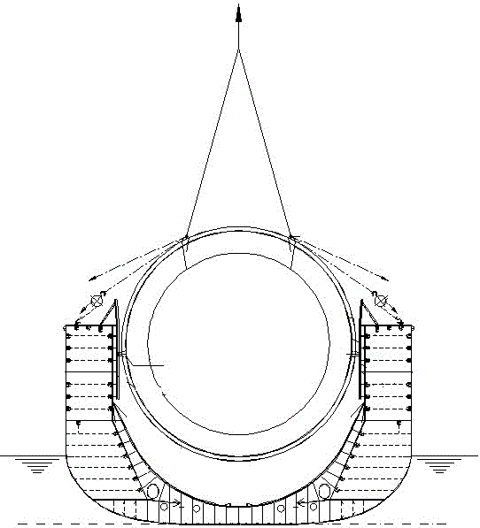
[0027] The invention relates to a quick and accurate positioning method for a liquid tank during the construction of a liquefaction ship, and the liquid tank is a large liquid tank larger than 10,000 cubic meters.

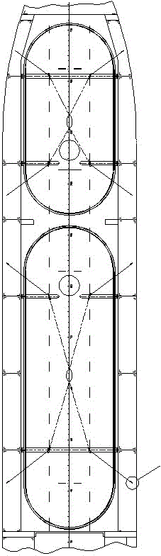
[0028] Such as figure 2 As shown, the positioning method of the liquid tank of the present invention includes the following steps:

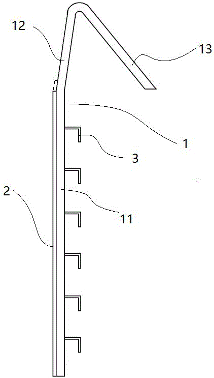
[0029] (1) Guide plates are arranged on both sides of the liquid tank with a circular cross section. The guid...


PUM


Abstract

The invention relates to a method for positioning a liquid tank quickly and accurately during the building of a liquefied ship. The method comprises the following steps: setting a guide plate and a lifting point on the liquid tank separately; mounting a detachable guide device in the mounting position of the liquid tank on a ship body segment; welding an operating eye plate on a deck, connecting a steel wire rope on hoisting equipment on the lifting point to lift the liquid tank above the mounting position, and connecting a chain block with the lifting point and the operating eye plate separately to position the liquid tank; pouring epoxy resin at the mounting position of the liquid tank, starting the hoisting equipment to enable the liquid tank to fall down, controlling the falling stability of the liquid tank by the chain block, and enabling the guide plate to clamp in the specially designed guide device; enabling the liquid tank to fall down to the mounting position quickly under accurate control; dismantling the steel wire rope and the chain block and dismantling the reusable guide device. The one-time positioning method provided by the invention has the characteristics of accuracy and quickness in hoisting, and the dismantled guide device can be reused repeatedly after hoisting.

Description

technical field [0001] The invention relates to ship construction, especially a method for quickly and accurately hoisting, guiding and positioning a liquid tank during the construction of a C-type independent cabin type liquefied gas ship. Background technique [0002] LNG ships mainly store and transport natural gas through liquid tanks, and the more common LNG ships are LNG ships with C-type independent tanks. The liquefied natural gas ship that needs to be built at present is a large liquid tank with a storage capacity of more than 10,000 cubic meters. On LNG ships, in order to ensure stability and safety, the gap between the liquid tank and the bulkhead is very small, but the mass of the liquid tank itself is very large. During the construction process, most of the hoisting work related to the liquid tank is carried out on the river surface. Any small tidal fluctuation or wave fluctuation will cause fluctuations in the floating crane and the construction ship, which wi...

Claims


Application Information

Patent Timeline
Patent Type & Authority Applications(China)
IPC IPC(8): B63B9/00B63B9/06
CPCB63B71/00B63B73/00
Inventor 金燕子王忠强
Owner HUDONG ZHONGHUA SHIPBUILDINGGROUP
Why Eureka
Try Eureka