Push-lock type unpowered container spreader

A container spreader and push-lock technology, which is applied in the spreader field, can solve the problems of complex structure, high cost, and increase the weight of the spreader, and achieve the effects of easy manufacture, simple structure and reasonable stress.

Inactive Publication Date: 2017-05-31
WUHAN UNIV OF TECH
View PDF5 Cites 5 Cited by
  • Summary
  • Abstract
  • Description
  • Claims
  • Application Information

AI Technical Summary

Problems solved by technology

At present, the spreaders used in container cranes are mostly driven by hydraulic motors, hydraulic cylinders or electric motors. Although the degree of automation is high and the operation is simple, it greatly increases the weight of the spreader, the structure is complex, and the cost is high. It seems very uneconomical, which provides a certain development space for the unpowered automatic container spreader with a relatively simple structure.
[0003] Lou Jin pointed out in "Design of Unpowered Container Spreader" that the existing unpowered automatic container spreader mostly adopts a space four-bar linkage mechanism with gaps, but the drive wheel does not move when the mechanism transmits the rotation lock opening and closing movement. Under normal circumstances, the driven wheel may also rotate, so the opening and closing of the twist lock has certain uncertainty. If there is a slight design and manufacture improperly, the spreader will have potential safety hazards; a Chinese invention patent application CN103818817A discloses a non-powered automatic Type container spreader device, but the device has obvious stress problems, the sliding claws cannot bear the container weighing tens of tons, and the device is prone to up and down movement during transportation, and the stability needs to be improved

Method used


Image

  • Push-lock type unpowered container spreader
  • Push-lock type unpowered container spreader
  • Push-lock type unpowered container spreader

Examples


Embodiment Construction

[0029] The present invention will be further described below in conjunction with the embodiments and accompanying drawings, but the present invention is not limited.

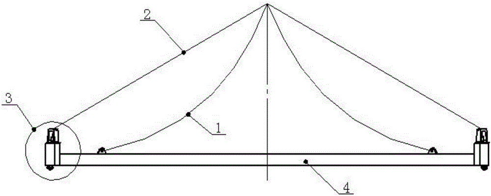
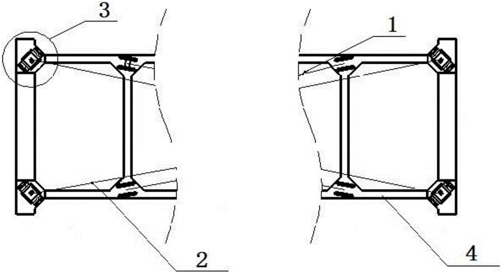
[0030] The push-lock type unpowered container spreader provided by the present invention has a structure such as figure 1 and figure 2 As shown, it includes a spreader frame 4, a main steel wire rope 1, an auxiliary steel wire rope 2, and a twist lock operating mechanism 3, wherein: there are four twist lock operating mechanisms 3, which are respectively located on the four corners of the spreader frame 4, and the spreader frame 4 and The stiffness and strength of the main steel wire rope 1 and the auxiliary steel wire rope 2 meet the actual work requirements, and the four main steel wire ropes 1 and the four auxiliary steel wire ropes 2 must be arranged symmetrically. There are 8 wire ropes in the whole spreader, among which 4 auxiliary wire ropes are connected to the push lock assembly and the lifting rope o...


PUM


Abstract

The invention discloses a push-lock type unpowered container spreader. The spreader comprises a spreader frame (4), main steel wire ropes (1), auxiliary steel wire ropes (2) and spin lock control mechanisms (3). The four spin lock control mechanisms (3) are located at the four corners of the spreader frame (4) correspondingly. The four main steel wire ropes (1) and the four auxiliary steel wire ropes (2) are arranged symmetrically. One end of each of the four auxiliary steel wire ropes is connected with a push-lock assembly (5) of the corresponding spin lock control mechanism (3), and the other end of each auxiliary steel wire rope is connected with a lifting rope of a hoisting machine. One end of each of the four main steel wire ropes is fixed to the inner side of the spreader frame, and the other end of each main steel wire rope is connected with the corresponding lifting rope. The spreader has the beneficial effects of being simple in structure, easy to manufacture, environment-friendly and low in cost, saving energy and the like; and when used for lifting or unloading a container in freight storage, water transport ports and wharfs, the spreader is reliable in motion, and the defect of up-and-down moving does not exist.

Description

technical field [0001] The invention relates to a spreader, in particular to a push-lock type non-powered container spreader. Background technique [0002] Container spreader is a large-scale special machine tool for container loading, unloading and transshipment. It is widely used in freight storage, water transport ports and wharves. It is an important auxiliary machine tool for lifting equipment. At present, the spreaders used in container cranes are mostly driven by hydraulic motors, hydraulic cylinders or electric motors. Although the degree of automation is high and the operation is simple, it greatly increases the weight of the spreader, the structure is complex, and the cost is high. It seems very uneconomical, which provides a certain development space for the unpowered automatic container spreader with a relatively simple structure. [0003] Lou Jin pointed out in "Design of Unpowered Container Spreader" that the existing unpowered automatic container spreader mos...

Claims


Application Information

Patent Timeline
Patent Type & Authority Applications(China)
IPC IPC(8): B66C1/12
CPCB66C1/101B66C1/12
Inventor 王国贤杜学良李伟
Owner WUHAN UNIV OF TECH
Why Eureka
Try Eureka