A kind of slewing crane around the pile

A crane and pile winding technology, applied in the directions of crane, transportation and packaging, can solve the problems of separation of the surface of the roller and the slewing support ring, and achieve the effect of avoiding the surface being crushed and avoiding damage

Active Publication Date: 2018-08-07
WUHAN MARINE MACHINERY PLANT
View PDF6 Cites 0 Cited by
  • Summary
  • Abstract
  • Description
  • Claims
  • Application Information

AI Technical Summary

Problems solved by technology

[0006] In order to solve the problem that some rollers may be separated from the surface of the slewing support ring in the prior art, an embodiment of the present invention provides a pile-wrapping slewing crane

Method used


Image

  • A kind of slewing crane around the pile
  • A kind of slewing crane around the pile
  • A kind of slewing crane around the pile

Examples


Embodiment Construction

[0031] In order to make the objectives, technical solutions, and advantages of the present invention clearer, the embodiments of the present invention will be described in further detail below in conjunction with the accompanying drawings.

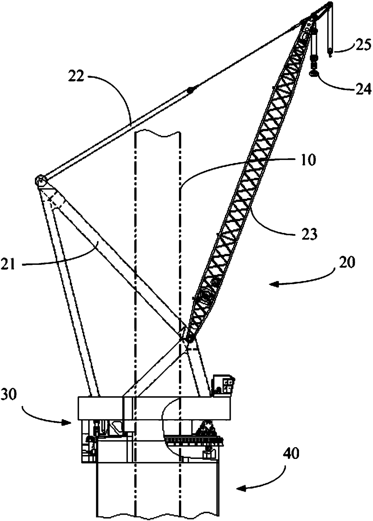
[0032] figure 1 It is a schematic structural diagram of a slewing crane around piles provided by an embodiment of the present invention, such as figure 1 As shown, the slewing crane can be set on the leg 10 of the offshore platform. The slewing crane includes a lifting mechanism 20, a slewing platform 30, and a base 40. The slewing platform 30 is provided on the upper end of the base 40, and the lifting mechanism 20 is provided on the slewing On platform 30.

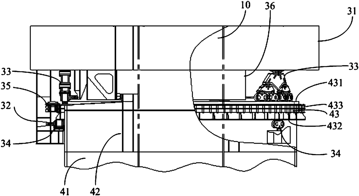
[0033] figure 2 It is a partial schematic diagram of a pile-around slewing crane provided by an embodiment of the present invention, such as figure 2 As shown, the base 40 includes a fixed seat 41, a cylindrical support column 42 and a slewing support ring 43. One end of the cylindrical ...


PUM


Abstract

The invention discloses a pile-around revolving crane and belongs to the field of cranes. The pile-around revolving crane comprises a lifting mechanism, a revolving platform and a base. The revolving platform is arranged at the upper end of the base, the lifting mechanism is arranged on the revolving platform, the base comprises a fixed base, a cylindrical supporting column and a revolving supporting ring, one end of the cylindrical supporting column is connected to the fixed base, and the other end of the cylindrical supporting column is connected to the revolving supporting ring. The revolving platform comprises a rotary table, a forward roller assembly and a backward roller assembly. The forward roller assembly is arranged on the rotary table, and the backward roller assembly is arranged on the rotary table through a backward roller supporting base. The forward roller assembly and the backward roller assembly each comprise a roller support and a roller, wherein the roller support is rotationally connected to the rotary table or the backward roller supporting base, and the roller rolls on the upper and lower surfaces of the revolving supporting ring along with rotation of the revolving platform. Due to the fact that the revolving plane of each roller support is parallel to the revolving axis of the revolving platform, when the surface of the revolving supporting ring is not flat, the roller supports will revolve to enable the rollers to press the revolving supporting ring.

Description

Technical field [0001] The invention relates to the field of cranes, in particular to a pile-around slewing crane. Background technique [0002] At present, pile-around slewing cranes are usually installed on the legs of various offshore platforms. They are widely used because of their small footprint, compact structure, large lifting capacity, and long lifting radius. [0003] The pile-around slewing crane mainly includes a base, a slewing platform and a lifting mechanism. The slewing platform is rotatably set on the base, and the lifting mechanism is set on the slewing platform. There is enough space in the middle of the base and the slewing platform. To enable the pile legs to pass through. In a small pile-around slewing crane, the slewing platform and the base are usually connected by a slewing bearing. In a large pile-around slewing crane, the slewing platform and the base pass through Roller connection, specifically, a slewing support ring is set on the base, multiple positi...

Claims


Application Information

Patent Timeline
Patent Type & Authority Patents(China)
IPC IPC(8): B66C23/16B66C23/84B66C23/693B66C23/62
CPCB66C23/16B66C23/62B66C23/705B66C23/84B66C2700/03
Inventor 蒋文革姬红斌何鹏雷旭叶凯陈云翼江辉任攀
Owner WUHAN MARINE MACHINERY PLANT
Why Eureka
Try Eureka