
Electric power maintenance ladder

A technology of electric power maintenance and vertical poles, which is applied in the direction of ladders, buildings, building structures, etc., can solve problems such as maintenance ladder slipping, physical hazards of staff, hidden safety hazards of maintenance personnel, etc., to ensure stability and firmness, and facilitate climbing operations. The effect of preventing the danger of falling

Inactive Publication Date: 2017-05-31
YANCHENG POWER SUPPLY CO STATE GRID JIANGSU ELECTRIC POWER CO +2
View PDF6 Cites 1 Cited by
  • Summary
  • Abstract
  • Description
  • Claims
  • Application Information

AI Technical Summary

Problems solved by technology

[0002] In electric power maintenance, it is often necessary to use power maintenance ladders. During the maintenance process, it is necessary to lean the maintenance ladders against supports such as walls and poles, and maintenance workers climb up the maintenance ladders to overhaul the electrical equipment above. In slippery conditions, when maintenance workers climb up the maintenance ladder, the maintenance ladder will slip along the lower part of the vertical bar, causing accidents and bringing safety hazards to the maintenance personnel
[0003] When the power maintenance ladder is leaning against the cylindrical power pole, the upper part is easy to slide. If the power maintenance ladder slides away from the power pole, the power maintenance ladder will collapse, and the maintenance workers will fall from high altitude, which is very dangerous
[0004] Thunderstorms often occur in summer, and when the staff are working on the maintenance ladder, the sudden thunder will cause harm to the staff's health and even life-threatening

Method used


Image

  • Electric power maintenance ladder

Examples


Embodiment Construction

[0021] The following examples can enable those skilled in the art to understand the present invention more comprehensively, but the present invention is not limited to the scope of the described examples.

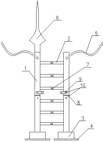
[0022] like figure 1 As shown, an electric maintenance ladder includes a support vertical bar 1 and a cross bar 2. The support vertical bar 1 and the cross bar 2 are all coated with a luminous coating, which emits light at night to remind the vehicle that someone is nearby. The two support vertical bars 1 are connected by several cross bars 2, the two support vertical bars 1 are fixed on the base 3, and the bottom of the base 3 is provided with a rubber pad 4, the area of ​​the rubber pad 4 is larger than the area of ​​the base 3, increasing the It reduces friction and ensures the stability and firmness of the maintenance ladder.

[0023] A strap 5 is fixed on the tops of the two supporting vertical bars 1. When in use, the two straps can be bound together around the power...


PUM


Abstract

The invention discloses an electric power maintenance ladder. The electric power maintenance ladder comprises supporting vertical rods and cross bars, wherein the two supporting vertical rods are connected through a plurality of cross bars and fixed on bases; a rubber pad is arranged at the bottom of each base; a binding band is fixed at the top of each supporting vertical rod; a lightning rod is inserted and fixed at the top end of one supporting vertical rod; the cross bars are retractable, insertion holes are formed in the retractable cross bars, and the cross bars are fixed through bolts; the supporting vertical rods are foldable, a rotating shaft and a fixing plate are arranged in the middle of each supporting vertical rod, and the fixing plate is connected with the corresponding supporting vertical rod through a movable bolt. The electric power maintenance ladder has the advantages as follows: the top of the electric power maintenance ladder cannot be separated from an electric pole, and the falling risk is effectively prevented; the lightning rod is inserted and fixed at the top end of one supporting vertical rod, so that an operator is prevented from being injured by lightning stroke.

Description

technical field [0001] The invention relates to the technical field of electric auxiliary tools, in particular to an electric maintenance ladder. Background technique [0002] In electric power maintenance, it is often necessary to use power maintenance ladders. During the maintenance process, it is necessary to lean the maintenance ladders against supports such as walls and poles, and maintenance workers climb up the maintenance ladders to overhaul the electrical equipment above. In a slippery situation, when maintenance workers climb up the maintenance ladder, the maintenance ladder will slip along the lower part of the vertical bar, causing accidents and bringing potential safety hazards to the maintenance personnel. [0003] When the power maintenance ladder leans against the cylindrical power pole, the upper part is easy to slide. If the power maintenance ladder slides away from the power pole, the power maintenance ladder will collapse, and maintenance workers will fal...

Claims


Application Information

Patent Timeline
Patent Type & Authority Applications(China)
IPC IPC(8): E06C1/383E06C7/08E06C7/46E06C7/00E06C1/34
CPCE06C1/383E06C1/34E06C7/00E06C7/08E06C7/46
Inventor 王鑫吴楠曾海建
Owner YANCHENG POWER SUPPLY CO STATE GRID JIANGSU ELECTRIC POWER CO
Learn More