
Train brake pad

A technology for brake pads and trains, which is applied in the direction of brake types, brake parts, friction linings, etc., can solve the problems of easy eccentric wear, large difference in thickness between the inner and outer rings of friction blocks, and easy cracks, etc., and achieve the friction coefficient Stable, reduce the probability of injury, and solve the effect of eccentric wear

Active Publication Date: 2017-05-31
CRRC CHANGZHOU TECH MARK IND CO LTD +1
View PDF10 Cites 10 Cited by
  • Summary
  • Abstract
  • Description
  • Claims
  • Application Information

AI Technical Summary

Problems solved by technology

Chinese patent document CN205298361U discloses a powder metallurgy brake pad, the friction block and the steel back are fixedly connected, the brake pad has no angle adjustment and floating adjustment during braking, the friction block cannot be adjusted by itself, and cracks and defects are prone to occur and other phenomena; and due to the inconsistent radial velocity of the brake disc, the thickness difference between the inner and outer rings of the friction block is large, and eccentric wear is very easy to occur
The above-mentioned floating brake pad is equipped with a disc spring between the friction block and the back plate, so that the angle of the friction block can be changed by the disc spring to increase the effective friction area, thereby reducing the partial wear of the friction block, but the disc spring has a large impact on the friction The angle adjustment of the block is limited, so the phenomenon of eccentric wear of the friction block has not been completely solved, and there is a risk of elastic floating failure of the butterfly spring in actual conditions, that is, when braking under adverse conditions such as complex and harsh environments, high temperature, high pressure, and high speed.

Method used


Image

  • Train brake pad
  • Train brake pad
  • Train brake pad

Examples


Embodiment 1

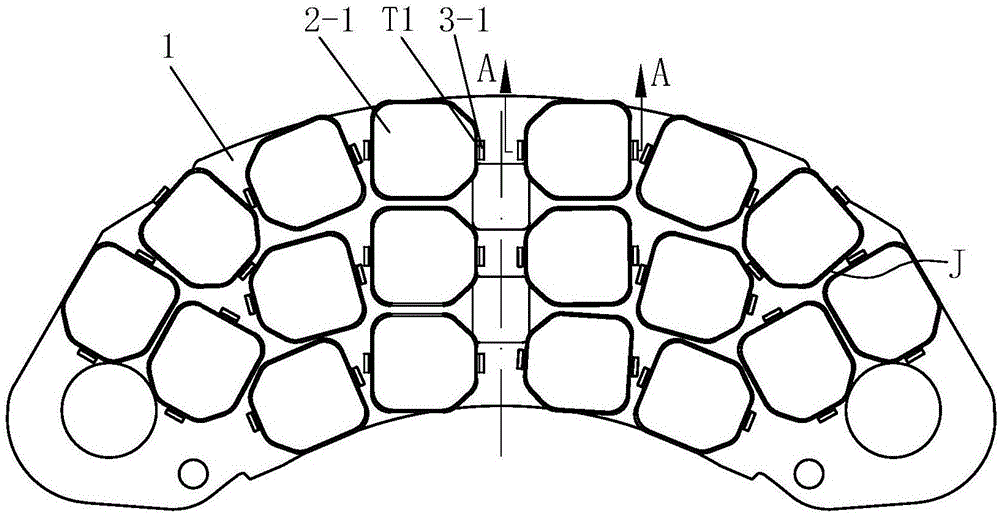
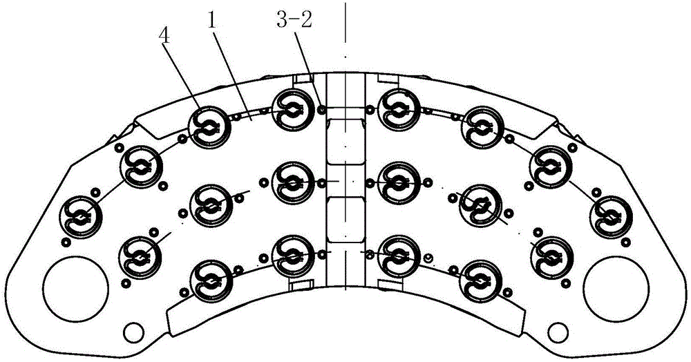
[0026] See Figures 1 to 10 , the present embodiment has a back plate 1, the back plate 1 is waist-shaped, and 18 friction blocks 2 are arranged on the back plate 1, and the number of friction blocks 2 is set according to the specifications of the brake pads. Correspondingly, 18 installation holes 1-a are provided on the backplane 1, and positioning holes 1-d are provided on both sides of each installation hole 1-b. The distribution of the friction blocks 2 on the back plate 1 is left-right symmetrical, and the friction blocks 2 are arranged in three arc lines, and the friction blocks 2 on the three arc lines are 4, 6, and 8 respectively.

[0027] The friction block 2 includes a friction body 2-1 and a support body 2-2. The friction body 2-1 is a hexagon with large and small ends. The shape of the hexagon is composed of a rectangle E and an isosceles trapezoid F. One end of the isosceles trapezoid F is a trumpet-shaped small end. The friction body 2-1 has six The straight si...


PUM


Abstract

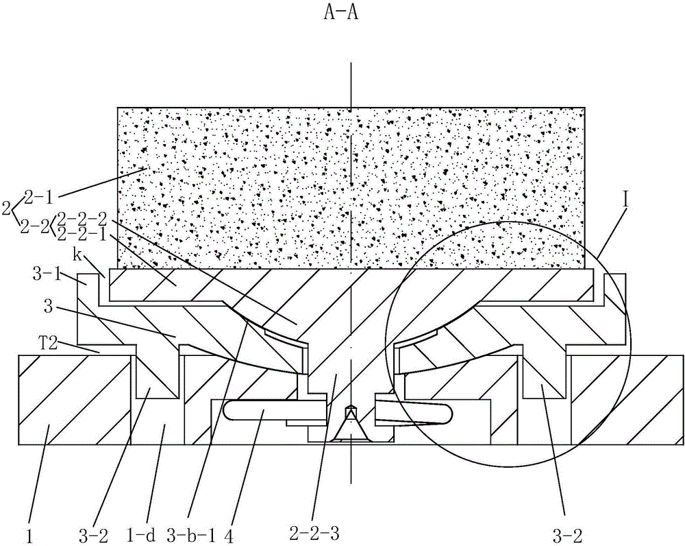
The invention discloses a train brake pad; a plurality of friction blocks are arranged on a back plate; each friction block comprises a friction body and a support body; each support body consists of a plate body, a table body and a pin body; a downward convex spherical face is formed in the middle of the bottom surface of each adjustment seat; each adjustment seat is provided with a middle hole; the upper part of each middle hole is expanded around to form a two-step-shaped spherical face; the friction blocks sit on upper-step spherical faces of the middle holes through the table bodies of the support bodies; a gap is formed between one support body and the top surface of one adjustment seat correspondingly; pin bodies pass through the middle holes in a loosening manner; the upper part of each mounting hole is expanded around to form a concave spherical face; the adjustment seats sit on the concave spherical faces of a mounting seat through the downward convex spherical faces; two locating pins of each adjustment seat are inserted into two corresponding locating holes in the back plate in a loosening manner; a gap is formed between the peripheral edge of the bottom surface of each adjustment seat and the top surface of the mounting seat; spring clamp rings are arranged at the lower parts of the pin bodies; and the friction blocks, the adjustment seats and the back plate are connected in a floating manner by the spring clamp rings. Multidimensional adjustment on the friction blocks is realized, a situation that the surfaces of the friction blocks are in 100% contact with the surface of the train brake pad all the time is ensured, and the eccentric wear problem of train brake pad is solved.

Description

technical field [0001] The invention relates to train brake pads. Background technique [0002] At present, the braking method of high-speed trains mainly relies on the mutual friction between brake pads and brake discs. Chinese patent document CN205298361U discloses a powder metallurgy brake pad, the friction block and the steel back are fixedly connected, the brake pad has no angle adjustment and floating adjustment during braking, the friction block cannot be adjusted by itself, and cracks and defects are prone to occur and other phenomena; and because the radial velocity of the brake disc is inconsistent, the friction block has a large difference in the thickness of the inner and outer rings, which is very prone to eccentric wear. Chinese patent document CN104455105A discloses a floating brake pad, which includes a back plate formed by splicing and connecting two back plates, several friction blocks arranged on the back plate, A disc spring between the block and the ba...

Claims


Application Information

Patent Timeline
IPC IPC(8): F16D65/092F16D69/04
Inventor 谢鑫林朱松潘祺睿
Owner CRRC CHANGZHOU TECH MARK IND CO LTD
Learn More