Heat-recovery air flue system used for kiln

A heat recovery and air duct technology, used in furnaces, waste heat treatment, furnace components, etc., can solve the problems of inability to guarantee the quality of ceramic tiles, energy waste, and difficulty in reusing the heat of roller kilns.

Pending Publication Date: 2017-05-31
GUANGDONG CHINA KILN TECH CO LTD
View PDF8 Cites 2 Cited by
  • Summary
  • Abstract
  • Description
  • Claims
  • Application Information

AI Technical Summary

Problems solved by technology

The atmosphere of the roller kiln is produced by combustion after mixing gas (fuel) and air. The firing problem can be solved by adjusting the atmosphere in the roller kiln reasonably. In actual operation, the temperature adjustment of different zones There is inaccurate adjustment, so there is no way to guarantee the quality of ceramic tiles; secondly, it is difficult to reuse the heat of the roller kiln, resulting in a lot of waste of energy

Method used


Image

  • Heat-recovery air flue system used for kiln
  • Heat-recovery air flue system used for kiln
  • Heat-recovery air flue system used for kiln

Examples


Embodiment Construction

[0018] The present invention will be further described below in conjunction with specific examples.

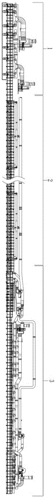
[0019] In this embodiment, a heat recovery air duct system for a kiln is provided with a preheating zone 1 , a firing zone 2 and a cooling zone 3 in sequence along the production direction of the kiln.

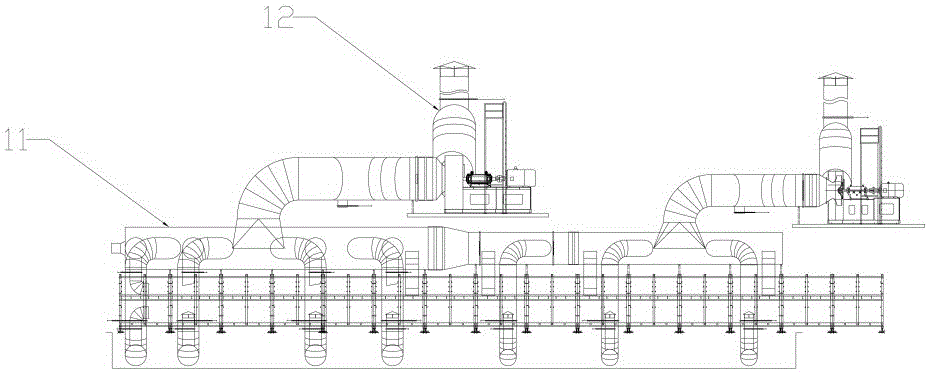
[0020] In this embodiment, the preheating zone 1 includes a smoke main pipe 11 and a two-stage smoke exhaust fan 12, and the smoke main pipe 11 is connected with the preheating zone 1 kiln and the two-stage smoke exhaust fan 12 respectively, wherein the smoke main pipe 11 is connected with the kiln road A plurality of smoking branch pipes are arranged to connect with each other. Through the above method, use the two-stage exhaust fan 12 to smoke the kiln, draw the smoke with heat generated in the firing zone 2 to the preheating zone 1 for preheating treatment, and at the same time discharge the smoke out of the kiln through the exhaust fan middle.

[0021] In this embodiment...


PUM


Abstract

The invention provides a heat-recovery air flue system used for a kiln. In a kiln path production direction, the heat-recovery air flue system is sequentially equipped with a pre-heating region, a firing region and a cooling region, wherein the pre-heating region comprises a smoke-exhausting main tube and at least one primary smoke exhaust fan; the firing region comprises a combustion-supporting air main tube, a plurality of groups of combustion-supporting air branch tubes, at least one upper combustion-supporting air branch tube and at least one lower combustion-supporting air branch tube, which are connected with each group of combustion-supporting air branch tubes; and the cooling region comprises a heat extraction air tube, a first combustion-supporting branch tube, a second combustion-supporting branch tube, a front-cooling air inlet tube and a tail-cooling air inlet tube. In this way, air flue systems among the pre-heating region, the firing region and the cooling region of the heat-recovery air flue system are matched with one another, so that sufficient utilization of heat in the kiln path is realized.

Description

technical field [0001] The invention relates to the technical field of a roller kiln, in particular to a heat recovery air duct system for a kiln. Background technique [0002] The roller kiln consists of a preheating zone, a firing zone and a cooling zone. It has the characteristics of uniform temperature and suitable for rapid firing. The atmosphere of the roller kiln is produced by combustion after mixing gas (fuel) and air. The firing problem can be solved by adjusting the atmosphere in the roller kiln reasonably. In actual operation, the temperature adjustment of different zones There is inaccurate adjustment, so there is no way to guarantee the quality of ceramic tiles; secondly, it is difficult to reuse the heat of the roller kiln, resulting in a lot of waste of energy. [0003] In actual operation, kiln operators will change the atmosphere of the kiln to solve certain firing problems, resulting in various problems; for example: 1. To increase the firing temperature ...

Claims


Application Information

Patent Timeline
Patent Type & Authority Applications(China)
IPC IPC(8): F27D17/00F23L15/00
CPCF23L15/00F27D17/001F27D17/004Y02E20/34
Inventor 谭映山胡卫清
Owner GUANGDONG CHINA KILN TECH CO LTD
Why Eureka
Try Eureka