
Pressure induction touch control display and electronic equipment

A technology for touch display and electronic equipment, applied in the fields of instruments, electrical digital data processing, optics, etc., can solve the problems of restricting the structural design of the whole machine, increasing the assembly error of the whole machine, difficult mass production, etc., and improving the stability of the whole machine. and reliability, reduce the assembly error of the whole machine, and have good structural stability.

Pending Publication Date: 2017-05-31
HUAQIN TECH CO LTD
View PDF4 Cites 6 Cited by
  • Summary
  • Abstract
  • Description
  • Claims
  • Application Information

AI Technical Summary

Problems solved by technology

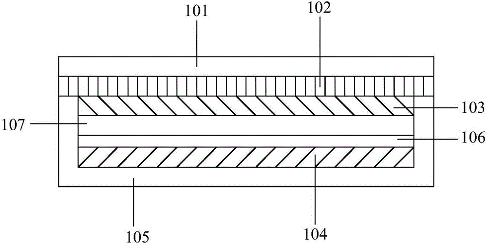
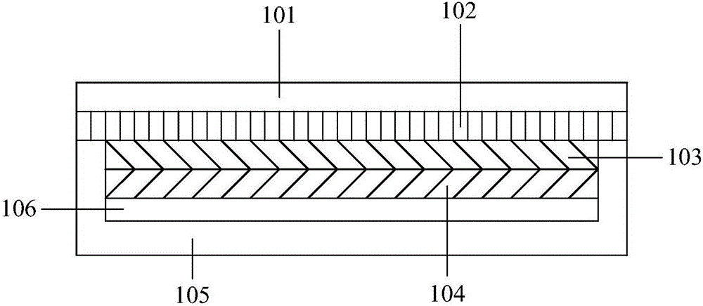
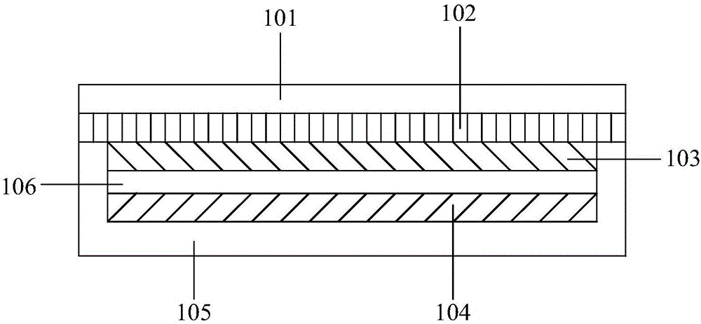
[0005] (1) The structural strength and structural stability of the electronic device display module are relatively low. When the electronic device falls or is hit, the structure between the display screen 103 and the pressure-sensitive layer 104 is likely to change, thereby affecting the touch screen. normal use; moreover, the separation design of the display screen 103 and the pressure-sensitive layer 104 will also increase the assembly error of the whole machine to a certain extent;
[0006] (2) In the prior art, the pressure-sensitive layer 104 is stacked on the middle frame 105, which increases the design requirements for the middle frame 105. The middle frame 105 needs to be as flat as possible and avoid digging holes, thereby limiting the structural design of the whole machine, and Difficult to mass produce

Method used


Image

  • Pressure induction touch control display and electronic equipment
  • Pressure induction touch control display and electronic equipment
  • Pressure induction touch control display and electronic equipment

Examples


Embodiment Construction

[0027] In order to make the purpose, technical solutions and advantages of the embodiments of the present invention more clear, various implementation modes of the present invention will be described in detail below in conjunction with the accompanying drawings. However, those of ordinary skill in the art can understand that, in each implementation manner of the present invention, many technical details are provided for readers to better understand the present application. However, even without these technical details and various changes and modifications based on the following implementation modes, the technical solution claimed in this application can also be realized.

[0028] The first embodiment of the present invention relates to a pressure-sensitive touch display, such as Figure 4 As shown, the pressure sensitive touch display includes: a frame body 1 , a display module 2 and a capacitive pressure sensing layer 3 .

[0029] Specifically, the capacitive pressure sensin...


PUM


Abstract

The embodiment of the invention relates to the technical field of computer input equipment, and discloses a pressure induction touch control display and electronic equipment. In the embodiment of the invention, the pressure induction touch control display comprises a frame body, a display module and a capacitance pressure induction layer; the capacitance pressure induction layer is internally embedded in the display module; the frame body comprises a metal bottom wall and a side wall connected to the metal bottom wall; the display module is fixed at the inner surface of the side wall, and an insulating buffer layer is arranged between the display module and the metal bottom wall. The invention further discloses the electronic equipment. According to the pressure induction touch control display and the electronic equipment, the capacitance pressure induction layer is internally embedded in the display module, thus the assembly error of a whole machine is lowered, the structure stability is good, the stability and the reliability of the whole machine are improved, and the pressure induction touch control display is suitable for batch production.

Description

technical field [0001] Embodiments of the present invention relate to the technical field of computer input devices, in particular to pressure-sensitive touch displays and electronic devices. Background technique [0002] At present, touch screens are mostly used in smart phones, e-books, tablet computers and other electronic devices, and capacitive touch screens are more common. Capacitive touch screens apply pressure sensing technology to touch screens, so Consumer electronics offer new modes of human-computer interaction. [0003] In the prior art, the structure of a display module of an electronic device using a capacitive touch screen is as follows: figure 1 , figure 2 and image 3 As shown, the display module generally includes: a glass cover 101, a touch screen 102, a display screen 103, a pressure sensing layer 104, and a backlight layer 107. In addition, due to different assembly processes, there is generally an air gap layer 106, wherein, The pressure sensing ...

Claims


Application Information

Patent Timeline
IPC IPC(8): G06F3/041G06F3/044G02F1/1333
CPCG02F1/13338G06F3/0412G06F3/0414G06F3/044
Inventor 叶金鑫
Owner HUAQIN TECH CO LTD
Learn More