Multi-gear vacuum on-load tap switch

An on-load tap, multi-gear technology, used in electrical switches, high-voltage/high-current switches, high-voltage air circuit breakers, etc. , shifting gears and other problems, to achieve the effect of prolonging the service life and high degree of automation

Inactive Publication Date: 2017-05-31
宁波安德奥电力设备有限公司
View PDF6 Cites 5 Cited by
  • Summary
  • Abstract
  • Description
  • Claims
  • Application Information

AI Technical Summary

Problems solved by technology

[0003] However, the moving contact of this type of vacuum tap changer is realized by the rotation of the main shaft, and the gear settings are distributed on a circular surface. The maximum number of gears is set at the factory and cannot be replaced flexibly.
Moreover, it is more laborious to change gears, and usually works with the gear shifting motor, and the switching speed is slow, so it is not suitable for high-frequency gear shifting operations
[0004] In addition, a switch with a permanent magnet structure, such as Patent No. CN201420176022.9 "A Bistable Permanent Magnet Mechanism", is provided with a magnetic core, an energy storage device, a magnetic control device, a limit device and an operating lever. The cooperation of the core and the permanent magnet can realize quick shifting, but since the electromagnetic coil can only generate magnetism and change the magnetic direction after being energized, the switch with this structure usually only has two or three gears, which cannot meet the needs of multiple gears. switch requirements

Method used


Image

  • Multi-gear vacuum on-load tap switch
  • Multi-gear vacuum on-load tap switch
  • Multi-gear vacuum on-load tap switch

Examples


Embodiment Construction

[0030] Embodiments of the present invention will be further described below in conjunction with the accompanying drawings.

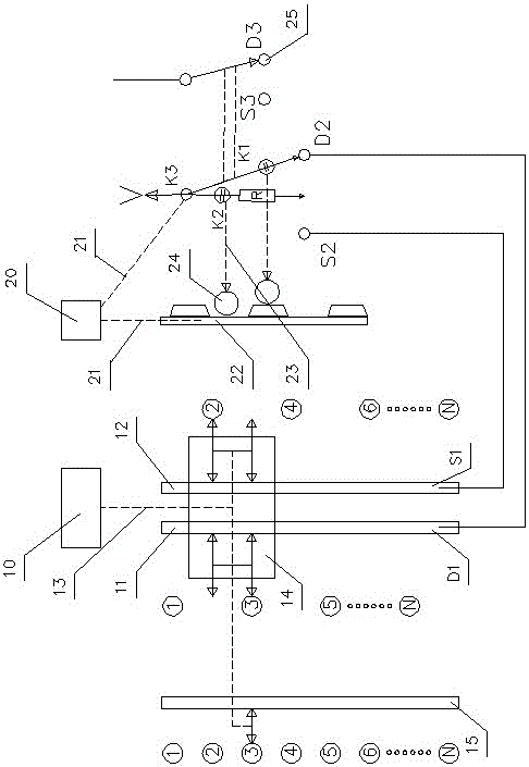
[0031] Such as figure 1 As shown, the multi-gear vacuum on-load tap-changer of the present invention is composed of a switch part and a selector switch part, and the switch part includes a gear position composed of a stepping motor 10, a screw rod 13, and a screw rod pair 14. Switch the drive mechanism and the static contact group composed of multiple sets of static contacts.

[0032] The static contacts are arranged at both ends of the screw rod respectively, and the odd and even numbers of static contacts are arranged alternately. The moving contact module is arranged on the screw pair. The moving contact module includes two independent moving contacts fixed on the screw pair, and the moving contact conductive rods 11 and 12. The two independent moving contacts are divided into It is an odd-number moving contact and an even-number moving contact, cor...


PUM


Abstract

The invention relates to a multi-gear vacuum on-load tap switch. The multi-gear vacuum on-load tap switch consists of two portions, i.e. a toggle switch and a selector switch, wherein the selector switch comprises a moving mechanism of a movable contact module consisting of a stepper motor, a lead screw and a lead screw pair and a gear selection mechanism consisting of a movable contact and multiple groups of static contacts; the static contacts of the selector switch are divided into an odd number group and an even number group, the static contacts of the odd number group contact a D movable contact, and the static contacts of the even number contact an S group of movable contacts; and the toggle switch comprises a permanent magnetic mechanism and a switching module, the access or a main circuit or the access of an auxiliary circuit is rapidly changed by virtue of an electromagnetic coil arranged on the switching module, the switching module is provided with two groups of vacuum pipes, the main circuit is provided with a main vacuum pipe, and the auxiliary circuit consists of the main vacuum pipe and a transition resistor which are connected in series. The multi-gear vacuum on-load tap switch is high in automation degree, simple in structure, and convenient to install and repair. The number of gears is not limited, and the size is smaller relative to a volume drum-type tap switch.

Description

technical field [0001] The invention relates to a multi-gear vacuum on-load tap changer, in particular to a multi-gear vacuum arc-extinguishing on-load tap switch which can be quickly shifted and is used by a power supply department. Background technique [0002] Most of the shift switches of current on-load multi-gear transformers adopt a disc-column structure, such as the patent No. 201610358806.7 "vacuum tap changer", which drives multiple sets of moving contacts to rotate synchronously by rotating the main shaft, and contacts with different static contacts respectively. , to achieve shifting operation under load conditions. On the basis of the on-load tap changer, a vacuum tube and a lever mechanism are added, and multiple rollers are installed inside the insulating cylinder. The front end of the lever is provided with a trapezoidal block, and the trapezoidal block cooperates with the roller when the main shaft rotates . The opening and closing of the vacuum tube is co...

Claims


Application Information

Patent Timeline
Patent Type & Authority Applications(China)
IPC IPC(8): H01H33/666H01H33/36H01H33/38H01H33/42H01H3/40H01F29/04
CPCH01H33/666H01F29/04H01H3/40H01H33/36H01H33/38H01H33/42
Inventor 史伟峰王吉庆
Owner 宁波安德奥电力设备有限公司
Why Eureka
Try Eureka