

Aluminum alloy battery box body for new energy automobile and preparation method of aluminum alloy battery box body
A new energy vehicle, aluminum alloy technology, applied in the direction of battery pack parts, circuits, electrical components, etc., can solve the problems of unsuitable safety, heavy weight, complicated processing technology, etc., and achieve scale production, box body Effects of weight reduction and simple manufacturing process
- Summary
- Abstract
- Description
- Claims
- Application Information
AI Technical Summary
Problems solved by technology
Method used
Image

Examples
Embodiment 1
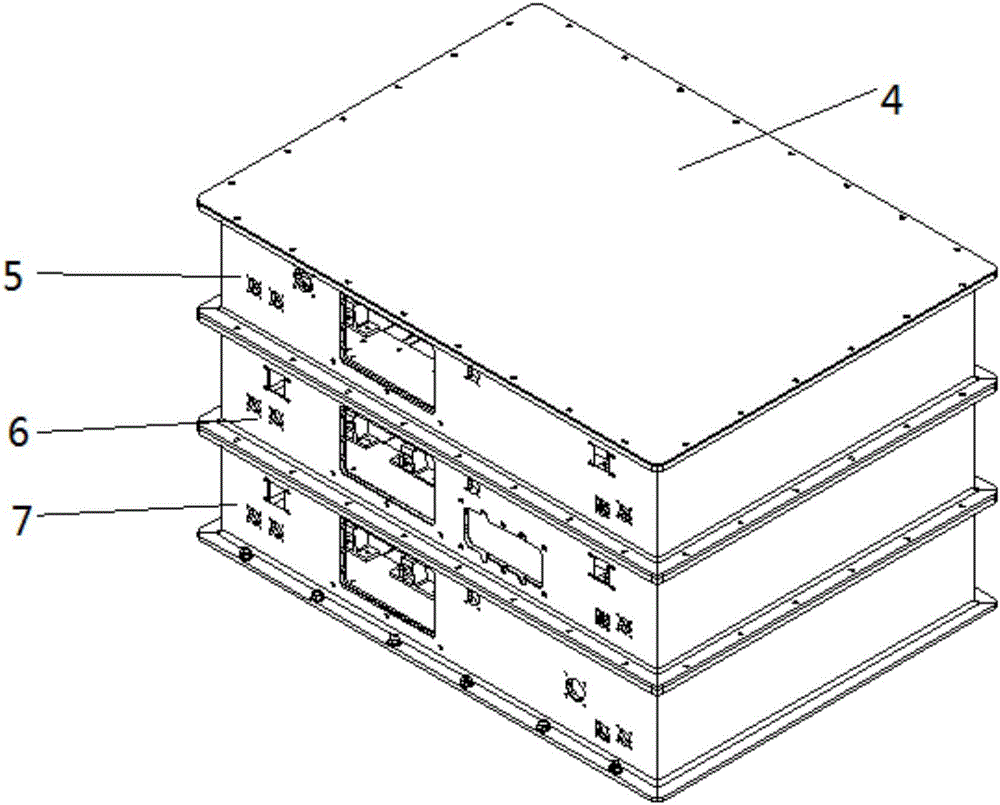
[0037] The invention provides an aluminum alloy battery case for a new energy vehicle, such as figure 1 Shown, comprise upper, middle and lower 3 combination boxes and box cover 4, between upper, middle and lower combination box (5,6,7) and described box cover 4 through the The mounting holes 9 are assembled with the bolts, and the sealing groove 15 of the combined box is provided with a gasket to play a sealing role.
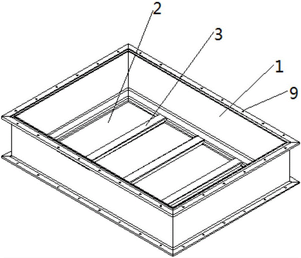
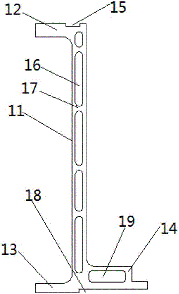
[0038] Among them, such as figure 2 and 4 As shown, the combined box body is an open structure surrounded by a bottom plate 2 and a box wall 1, and several bottom support beams 3 are fixed on the bottom plate 2, such as image 3 As shown, the box wall 1 includes a box wall main body 11 and transverse ribs positioned at the top and bottom ends of the box wall main body. The transverse rib 14, wherein the main body 11 of the box wall is a flat plate structure with a cavity 16 inside, and the cavity 16 is provided with a reinforcing rib 17. The setting of the...
PUM
 Abstract
Description
Claims
Application Information