Bidirectional tempering and thermal runaway anti-diffusion device for automobile power battery

A technology for automotive power batteries and thermal runaway, which is applied to secondary batteries, circuits, electrical components, etc., can solve the problems of uneven flow of coolant, high safety factor, and easy interference with circuits, so as to avoid thermal runaway and control The effect of own temperature

Pending Publication Date: 2017-05-31
SHANGHAI UNIV OF ENG SCI
View PDF8 Cites 9 Cited by
  • Summary
  • Abstract
  • Description
  • Claims
  • Application Information

AI Technical Summary

Problems solved by technology

[0008] The technical problem to be solved by the present invention is to provide a compact and efficient two-way temperature regulation and thermal runaway anti-diffusion device for automotive power batteries, which can solve the problems of insufficient heat exchange capacity, uneven flow of coolant, complex device structure, And it is easy to interfere with the circuit and other problems, which can avoid the risk of thermal runaway spreading to the surrounding batteries. In addition, the battery can start normally at low ambient temperature, and the structure is simple and compact. The output power of the battery per unit volume is high, which is convenient for processing and installation. High safety factor, good for long-term use, etc.

Method used


Image

  • Bidirectional tempering and thermal runaway anti-diffusion device for automobile power battery
  • Bidirectional tempering and thermal runaway anti-diffusion device for automobile power battery
  • Bidirectional tempering and thermal runaway anti-diffusion device for automobile power battery

Examples


Embodiment 1

[0071] Such as figure 1 In the shown embodiment of a plan A, several batteries 4 are tightly spaced in a matrix form on the square heat-conducting substrate 1, and the number of batteries 4 in each row is 4, and the fluid through holes 2 are axially connected to the batteries 4. The axial directions are perpendicular to each other, and the fluid through holes 2 are arranged in a matrix shape 5X3 on both sides of each row of batteries 4. The fluid through holes 2 between adjacent batteries 4 are shared, and the cross section of the fluid through holes 2 is vertical along the axis of the battery 4. The narrow rectangular arrangement, that is, the opening size of the fluid through hole 2 along the axial direction of the battery 4 is larger than the opening size perpendicular to the axial direction of the battery 4. On the premise of taking into account the mechanical shock resistance performance of the heat-conducting matrix and the output power of the battery module per unit volu...

Embodiment 2

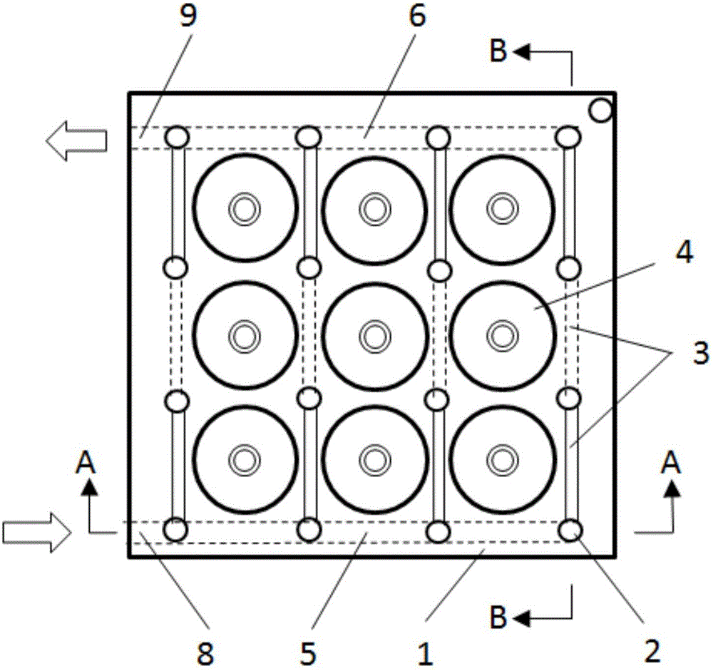
[0075] Such as Figure 2-5 In the shown embodiment of a B scheme, 9 batteries 4 are tightly spaced in a matrix-like vertical space on the square heat-conducting substrate 1, and the axial direction of the battery 4 is parallel to the axial direction of the circular fluid through hole 2. Each battery 4 is located at the center of four fluid through holes 2 , and the fluid through holes 2 between adjacent batteries 4 are shared.

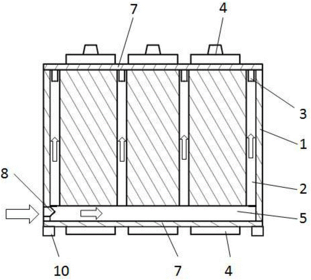
[0076] Corresponding to the ports of the fluid through holes 2 located on the outer surfaces of the top side and the bottom side of the heat conduction substrate 1, a number of connection grooves 3 are opened on the outer surfaces of the two sides respectively, and the cross sections of the connection grooves 3 are vertically arranged along the axial direction of the battery 4 The rectangle, that is, the opening width of the connecting groove 3 is less than the opening depth, such as image 3 As shown; the two ends of the connection groove 3 are conne...

Embodiment 3

[0083] Such as Figure 6 In another B-plan embodiment shown, 9 batteries 4 are tightly spaced in a matrix-like vertical space on the block-shaped heat-conducting substrate 1. The axial direction of the battery 4 and the axial direction of the fluid through hole 2 are parallel to each other. Each The battery 4 is located at the center of the four fluid through holes 2, and the fluid through holes 2 between adjacent batteries 4 are shared;

[0084] Corresponding to the ports of the fluid through holes 2 located on the outer surface of the top side and the bottom side of the heat conduction base 1, a number of connection grooves 3 are opened on the outer surfaces of the two sides respectively, and the two ends of the connection groove 3 are connected to two fluid through holes 2 located on the heat conduction base 1 The ports on the outer surface of the same side connect all the fluid through holes 2 in the heat conduction base 1 into four parallel flow channels, and the four flu...


PUM

PropertyMeasurementUnit
lengthaaaaaaaaaa
pore sizeaaaaaaaaaa

Abstract

The invention relates to a bidirectional tempering and thermal runaway anti-diffusion device for an automobile power battery. A plurality of battery mounting holes and fluid through holes are horizontally/vertically formed on a blocked heat-conducting matrix at intervals; a cylindrical battery tightly sleeves inside each battery mounting hole; the axial direction of the battery is vertical to or parallel to the axial direction of the fluid through holes; an inlet confluence slot and an outlet confluence slot which are communicated with the fluid through holes are formed on the heat-conducting matrix; at the two ends of the corresponding fluid through holes, a flat plate type sealing cover plate is respectively coated on each of the outer surfaces on the two opposite sides of the heat-conducting matrix; an inlet of the inlet confluence slot and an outlet of the outlet confluence slot are formed on the positions at the vertical slide of the heat-conducting matrix provided with the cover plate and close to the bottom side of the heat-conducting matrix; and a heat exchanger is communicated with the inlet of the inlet confluence slot and the outlet of the outlet confluence slot, so as to form a heat-conducting fluid circulating heat exchange channel. The device can be used for solving the problems of insufficient heat exchange capability, uneven battery temperature, complex device structure and easiness in interference with a circuit of the present heat management device and can avoid the risk in heat dispersing to the surrounding battery due to thermal runaway.

Description

technical field [0001] The invention relates to the field of electric vehicles, in particular to temperature control and thermal runaway anti-diffusion technologies for automotive power batteries. Background technique [0002] Automotive power batteries such as lithium-ion batteries have high energy density, small size, and long cycle life. They have great application potential and market in electric passenger cars and commercial vehicles. However, during the charging and discharging process, the temperature of lithium-ion batteries rises due to electrochemical heat generation and Joule heat generation, which affects power performance and cycle life. Excessively high temperatures even cause thermal runaway, leading to accidents such as spontaneous combustion and explosion. The decomposition temperature of the negative electrode protective film of lithium-ion batteries is 80-120 degrees Celsius, and the internal thermal runaway temperature is 150-175 degrees Celsius. Therefo...

Claims


Application Information

Patent Timeline
Patent Type & Authority Applications(China)
IPC IPC(8): H01M10/613H01M10/615H01M10/617H01M10/625H01M10/6568
CPCH01M10/613H01M10/615H01M10/617H01M10/625H01M10/6568Y02E60/10
Inventor 张恒运宋利民徐屾
Owner SHANGHAI UNIV OF ENG SCI
Why Eureka
Try Eureka