
Card edge connector

A card edge connector and contact part technology, applied in the direction of connection, fixed connection, computer peripheral equipment connector, etc., can solve the problems of unusable, no elasticity, plastic deformation, etc., and achieve the effect of increasing the length and reducing the positive pressure

Active Publication Date: 2017-05-31
FOXCONN (KUNSHAN) COMPUTER CONNECTOR CO LTD +1
View PDF5 Cites 8 Cited by
  • Summary
  • Abstract
  • Description
  • Claims
  • Application Information

AI Technical Summary

Problems solved by technology

Each conductive terminal is inserted and installed on both sides of the central slot from top to bottom. Each conductive terminal includes a base fixed to the insulating body, two extensions extending upwards from the base, and two extensions from the two extensions. The arc-shaped protruding parts protruding inward, because the thickness of the protruding parts in the horizontal direction is extremely large, they have no elasticity. When the circuit board module is inserted into the central slot, it can only rely on the extension part to deform. The extension part is straight, so the positive pressure between the conductive terminal and the circuit board module is extremely high, which easily causes the extension part of the conductive terminal to be plastically deformed, making it unusable

Method used


Image

  • Card edge connector
  • Card edge connector
  • Card edge connector

Examples


Embodiment Construction

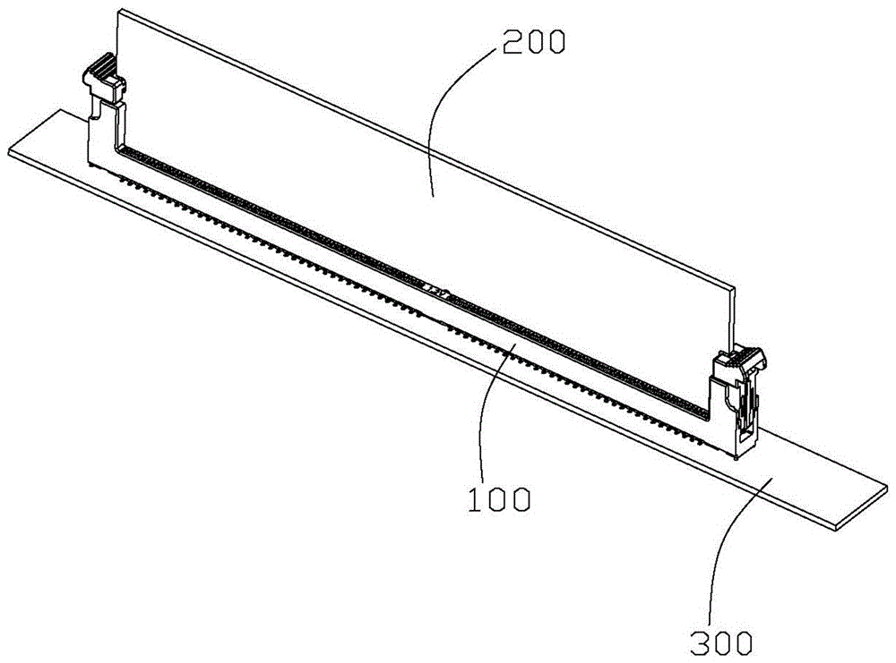
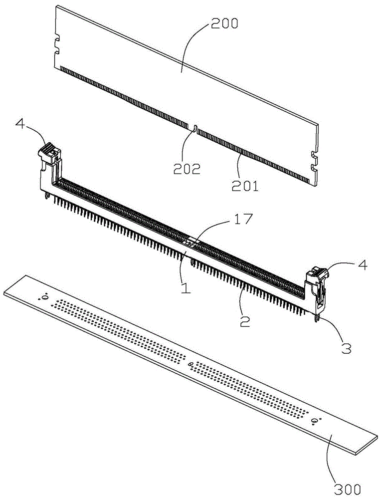
[0032] Such as Figure 1 to Figure 6 As shown, a card edge connector 100 is used for connecting a memory module 200 and an external circuit board 300 . The card edge connector 100 includes an insulating body 1 , a plurality of conductive terminals 2 and a plurality of hooks 3 fixed on the insulating body 1 , and locking arms 4 installed on both sides of the insulating body 1 .

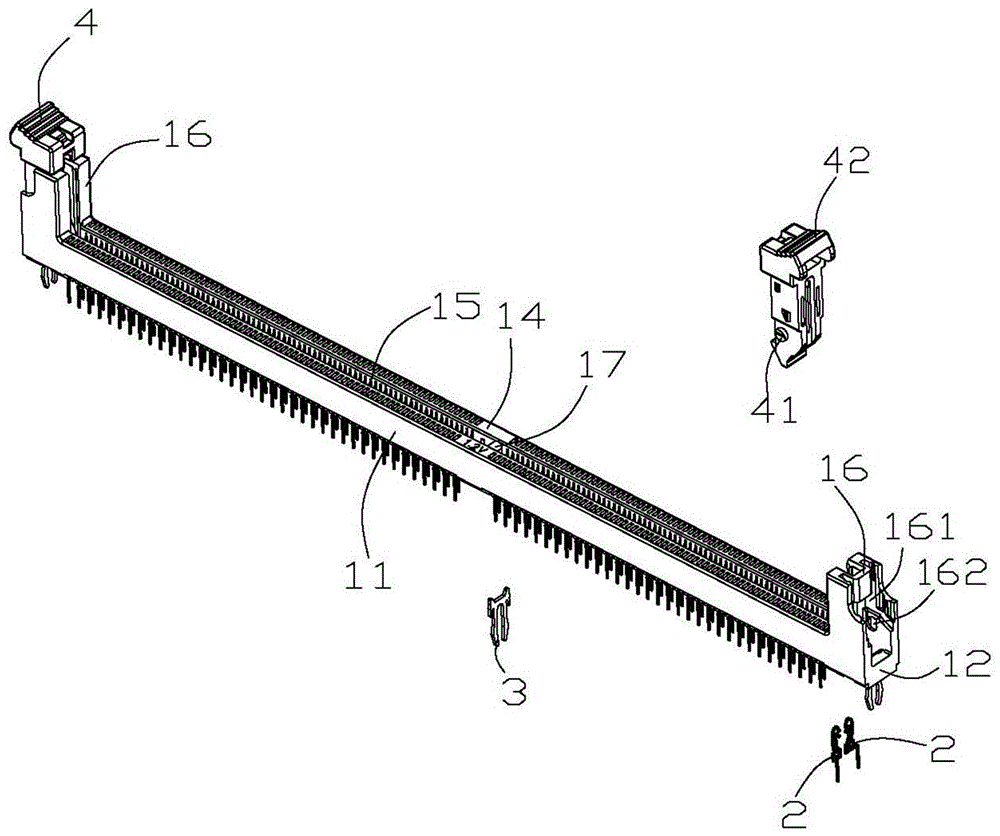
[0033] The insulating body 1 includes two side walls 11 extending along the longitudinal direction, two end walls 12 connecting the ends of the two side walls 11, a bottom wall 13 for being attached to an external circuit board, and a top wall opposite to the bottom wall 13 14. The two side walls 11 and the end wall 12 are surrounded to form a central slot 15, and each side wall 11 runs through a row of installation grooves 18 vertically through the bottom wall 13 and the top wall 14, and each installation groove 18 is along the insulating body. 1 runs through the central slot 15 in the width directi...


PUM


Abstract

The invention discloses a card edge connector comprising a longitudinal insulation body and a plurality of conductive terminals fixed on the insulation body, wherein the insulation body comprises two side walls extending along the longitudinal direction, end walls connecting tail ends of the two side walls, and a central slot encircled by the two side walls and the end walls; the plurality of conductive terminals are respectively installed on the two side walls; each terminal is provided with a base part fixed on the corresponding side wall, an installation part extending out of the insulation body from one end of the base part, two extending parts extending from the other end of the base part, and two contact parts respectively extending to the central slot from the two extending parts; the base part, the extending parts, the contact parts and the installation part of each conductive terminal are positioned on the same plane, the two extending parts comprise a first extending part close to the central slot and a second extending part far away from the central slot, the first extending part is bent for many times to reduce positive pressure of the conductive terminal.

Description

[0001] 【Technical field】 [0002] The invention relates to a card edge connector, in particular to a card edge connector with double-point contact. [0003] 【Background technique】 [0004] US Patent No. 7,637,783B discloses a card edge connector, which includes an insulating body with a central slot and two rows of conductive terminals mounted on both sides of the central slot. Each conductive terminal includes a mounting portion extending leftward, a base portion extending forward from the mounting portion and then bent rightward, and two separate extension portions extending backward from the base portion and extending upward. The two extension parts are respectively bent downward and rightward to form two contact parts extending downward and upward respectively, and the two contact parts are used for double-point contact with the memory module. A contact portion of the conductive terminal extends upwards, which is opposite to the insertion direction of the memory module, wh...

Claims


Application Information

Patent Timeline
Patent Type & Authority Applications(China)
IPC IPC(8): H01R12/73H01R13/02H01R12/57H01R12/58
CPCH01R12/737H01R12/721H01R2201/06H01R12/523
Inventor 徐琴李庄星唐文军
Owner FOXCONN (KUNSHAN) COMPUTER CONNECTOR CO LTD
Learn More