Combination method of microcomputer protection device and input protection device and output protection device

A microcomputer protection device and protection device technology, applied in the direction of emergency protection circuit devices, electrical components, etc., can solve problems such as unreliable performance, stop production of spare parts, no inventory, etc., to ensure safe operation, ensure stable operation, and save spare parts purchase Effect

Active Publication Date: 2019-03-29
SHANXI TAIGANG STAINLESS STEEL CO LTD
View PDF4 Cites 0 Cited by
  • Summary
  • Abstract
  • Description
  • Claims
  • Application Information

AI Technical Summary

Problems solved by technology

[0003] Almost all power systems have adopted microcomputer protection. Microcomputer protection has many advantages such as reliable performance, fast action, and powerful functions. However, due to its electronic components, the performance may become unreliable and prone to failure after a long service life; Very quickly, it will be replaced with a new model in two to three years, and the service life of the microcomputer protection is generally eight to ten years, which leads to a long service life of the protection device. Once some protection plug-ins fail, the spare parts have already been discontinued and there is no Serious Hidden Dangers of Inventory

Method used


Image

  • Combination method of microcomputer protection device and input protection device and output protection device
  • Combination method of microcomputer protection device and input protection device and output protection device
  • Combination method of microcomputer protection device and input protection device and output protection device

Examples


Embodiment Construction

[0049] The specific implementation manners of the present invention will be described below in conjunction with the embodiments and the drawings, but the following embodiments are only for understanding the present invention, and are not intended to limit the present invention.

[0050] Input protection device embodiment 1

[0051] The original original microcomputer relay protection device 3 of this embodiment is partially damaged, and the newly added new microcomputer relay protection device 4 is used to compensate for the function of the damaged part.

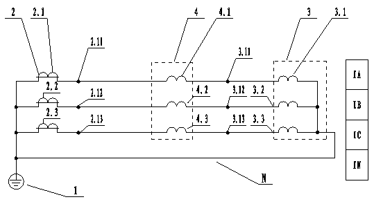
[0052] The schematic diagram of the current input circuit of the input protection device is shown in figure 1 , The right side of the figure is the protection current. It includes the ground wire 1, the neutral wire N, the current transformer 2 and the original microcomputer relay protection device 3. The neutral wire N is connected to the ground wire 1, the current transformer 2 of the current transformer A phase 2.1, the current ...


PUM


Abstract

The invention relates to a combination method of a microcomputer protection device, an input protection device and an exit protection device. According to the combination method, when part of plug-ins in an original microcomputer relay protection device of one manufacturing plant in a power supply system are damaged, a new microcomputer relay protection device of the other manufacturing plant is switched in to compensate functions of the damaged plug-ins of the original microcomputer relay protection device. According to the input protection device, the new microcomputer relay protection device of the other manufacturing plant is connected in series into the original microcomputer relay protection device of one manufacturing plant in the power supply system to compensate the functions of the damaged plug-ins of the original microcomputer relay protection device. According to the exit protection device, two trip contacts of the original microcomputer relay protection device are connected in parallel with a trip contact of the new microcomputer relay protection device of the other manufacturing plant. The combination method of the microcomputer protection device solves the difficult problem that when part of the plug-ins of the original microcomputer relay protection device are damaged, no accessories are provided. The input protection device and the exit protection device are two devices with good effects, which are used for implementing the combination method of the microcomputer protection device.

Description

Technical field [0001] The invention relates to a combination method of a microcomputer protection device, an input protection device and an exit protection device. Background technique [0002] The power system is composed of various types of electrical equipment. Due to factors such as manufacturing, transportation, installation, and operating environment, electrical equipment will inevitably have abnormalities or faults in actual operation. Relay protection is used to detect various electrical equipment in the power system. The operating status of the equipment, when the equipment is abnormal, the alarm will be issued. When the equipment fails, the relay protection will quickly, automatically, and selectively remove the faulty equipment to prevent the faulty original from more serious damage and ensure the normal operation of the non-faulty parts. Minimize the scope of the accident and the impact on the system, and ensure the stability of the power system. Misoperation and ref...

Claims


Application Information

Patent Timeline
Patent Type & Authority Patents(China)
IPC IPC(8): H02H7/00
CPCH02H7/00
Inventor 渠天清
Owner SHANXI TAIGANG STAINLESS STEEL CO LTD
Why Eureka
Try Eureka