Landing assist apparatus interface bulkhead and method of installation

a technology of landing assist and bulkhead, which is applied in the direction of anchoring installation, anchoring hook, transportation and packaging, etc., can solve the problems of specifically designed helicopters lacking other desirable features, aircraft/ship landing assist systems, etc., and achieve the effect of avoiding potentially catastrophic damage to helicopters

Active Publication Date: 2008-03-18
THE BOEING CO
View PDF5 Cites 60 Cited by
  • Summary
  • Abstract
  • Description
  • Claims
  • Application Information

AI Technical Summary

Benefits of technology

[0011]The present disclosure overcomes disadvantages of the prior art by providing an aircraft landing assist apparatus that is specifically designed to be retrofit to existing aircraft that have not previously been designed for shipboard landings. In addition, on rough landing of an aircraft using the apparatus, the apparatus is designed to collapse in a controlled manner beneath the aircraft, thereby avoiding any damage to ammunition and / or fuel storage areas of the aircraft, and preventing the transfer of the vertical loads due to impact to the pilot and / or copilot.
[0014]To provide sufficient structural strength to the aircraft structure to facilitate use of the aircraft landing assist apparatus, both the forward bulkhead wall and rearward bulkhead walls are removed and replaced by reinforced bulkhead walls. The reinforced bulkhead walls provide sufficient structural strength to the helicopter frame to support the rotor assembly and power unit of the aircraft, as well as support the landing assist apparatus of the disclosure.
[0019]The four stabilizing struts extending between the base and the probe hold the probe in its downwardly extending position. The strut resist movement of the probe when a compressive force on the probe exerts a tensile force on the struts. The struts are specifically designed to collapse when a compressive force is exerted on the struts. thereby providing no resistance of movement of the probe that exerts a compressive force on the struts. In this manner, the movement of the probe is controlled when an excessive impact force is exerted on the probe due to a hard landing of the helicopter on the ship deck. The controlled movement of the probe prevents the probe proximal end from piercing the bottom fuselage panel of the helicopter and potentially entering into the ammunition container or a fuel cells.
[0023]The distal ends of the stabilizing struts are operatively connected to the probe by a slip ring. The slip ring is mounted on the probe for movement of the slip ring along the probe length in response to a predetermined amount of movement of the probe distal end relative to the probe proximal end. This enables the slip ring to move relative to the probe in response to a significant impact of the probe distal end with a ship deck on a rough landing of the helicopter. The movement of the slip ring controls the collapse of the stabilizer struts and the movement of the probe in response to the impact.
[0024]The slip ring is provided with a lock mechanism that holds the slip ring stationary relative to the probe with the probe proximal and distal ends in their extended positions. On impact of the probe distal end with the ship deck, the slip ring continues to hold the stabilizer strut distal ends stationary relative to the probe for a predetermined movement of the probe distal end relative to the probe proximal end. The tension on the struts maintains the position of the probe relative to the helicopter. When movement of the probe distal end relative to the probe proximal end exceeds the predetermined amount of movement, the lock mechanism of the ring is released and the ring, as well as the attached stabilizer strut distal ends, are free to move along the length of the probe to control the collapse of the probe beneath the helicopter.
[0025]The aircraft landing assist apparatus of the disclosure described above enables existing helicopters to be retrofit with the apparatus, adapting the helicopters for shipboard landings. The apparatus is also constructed whereby it will controllably collapse in response to an excessive impact of the apparatus with a ship deck on rough landing of the helicopter, thereby avoiding potentially catastrophic damage to the helicopter.

Problems solved by technology

The prior art aircraft / ship landing assist systems are therefore disadvantaged in that the system are limited to use with helicopters that are dedicated for use with the landing assist system.
These specifically designed helicopters may be lacking in other desirable features for helicopters, for example the various different types of weaponry available on modern day military aircraft.
Should an excessive compressive force due to a rough landing be exerted against the probe distal end causing complete retraction of the probe distal end relative to the proximal end and exerting a compressive force on the probe proximal end, the small diameter journal wall first fail, causing the probe to collapse beneath the base and preventing the probe from being pushed upwardly through the center of the helicopter fuselage bottom panel and into the ammunition container in the helicopter bay.

Method used


Image

  • Landing assist apparatus interface bulkhead and method of installation
  • Landing assist apparatus interface bulkhead and method of installation
  • Landing assist apparatus interface bulkhead and method of installation

Examples


Embodiment Construction

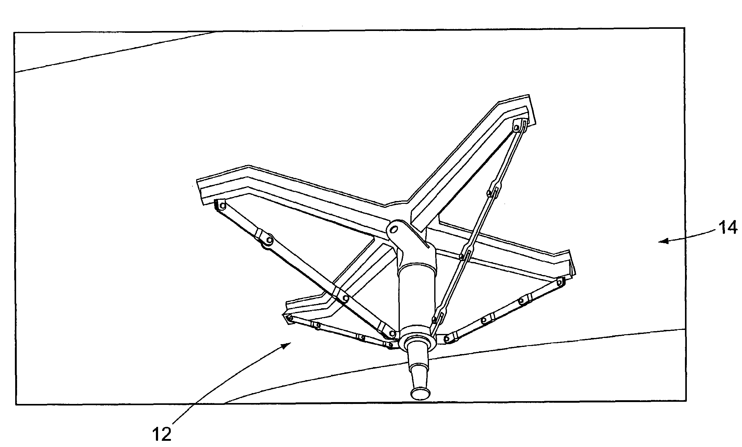
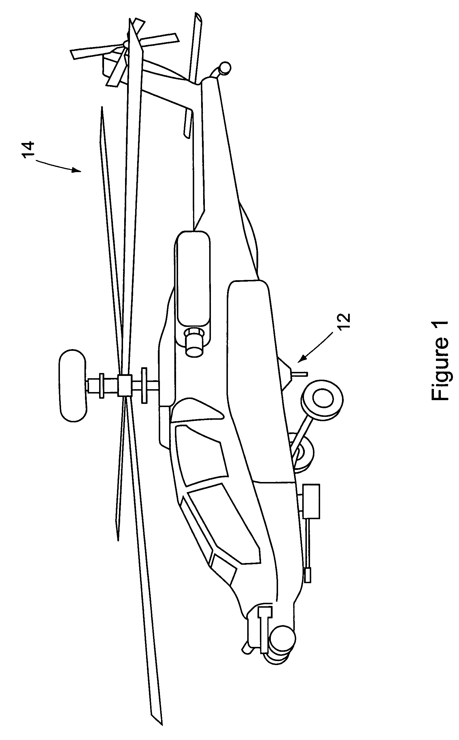
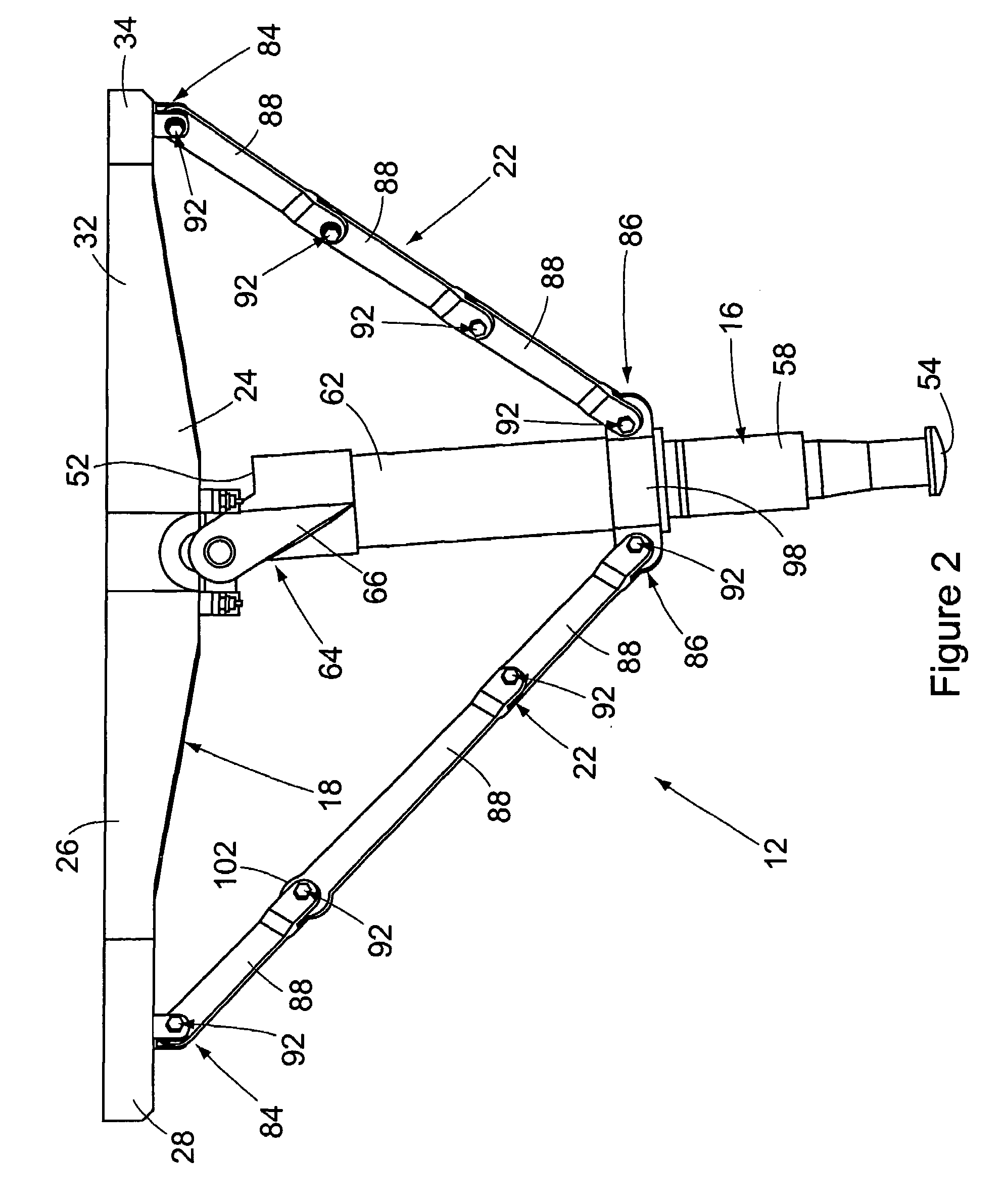
[0055]FIG. 1 shows the aircraft landing assist apparatus 12 of the disclosure employed on an aircraft 14. Specifically, FIG. 1 shows the apparatus 12 installed on the underside of a helicopter-type aircraft, for example an AH64 Apache helicopter. It should be understood that the particular type of aircraft 14 with which the apparatus 12 is shown in FIG. 1 is illustrative only. It is not intended that the apparatus 12 be limited to use with any one particular type of aircraft.

[0056]The apparatus 12 is specifically designed to be retrofit to existing helicopters that have not previously been designed for shipboard landings. In addition, on rough landing of the aircraft using the apparatus 12, the apparatus is designed to collapse in a controlled manner beneath the aircraft 14, thereby avoiding any damage to internal components of the aircraft such as an ammunition container and / or a fuel storage cell. Although an embodiment of the apparatus is retrofit to an existing aircraft, the app...


PUM


Abstract

An aircraft landing assist apparatus is designed to be retrofit to existing aircraft having internal constructions that have been modified to support the apparatus. The apparatus is designed so that on rough landings of the aircraft on a ship deck, the apparatus will collapse in a controlled manner to avoid any damage to ammunition and / or fuel storage areas of the aircraft.

Description

[0001]This was developed in the course of work under U.S. Government Army Contract DAAH23-99-C-0111. The U.S. government may possess certain rights in the present disclosure.BACKGROUND [0002](1) Field[0003]The present disclosure pertains to an aircraft landing assist system. More specifically, the present disclosure pertains to a mounting system for an aircraft landing assist probe, and a method of retrofitting an aircraft with the mounting system to adapt that aircraft for landing on a deck of a ship.[0004](2) Description of the Related Art[0005]Landing assist systems have been developed that facilitate the landing of an aircraft, for example, a helicopter, on the deck of a ship. An example of one such system is the aircraft / ship integrated secure and traverse (ASIST) deck landing system developed by Indal Technologies, Inc. of Ontario, Canada.[0006]In a typical aircraft landing assist apparatus employed in landing a helicopter on the deck of a ship, the helicopter is provided with...

Claims


Application Information

Patent Timeline
Patent Type & Authority Patents(United States)
IPC IPC(8): B64F1/12B64C25/00B64C25/10B64C25/32B64C25/68B64C27/04
CPCB64C1/062B64C25/00B64C25/10B64F1/125B64C25/68B64C25/32B64C2025/325B64C2211/00
Inventor MUYLAERT, NEAL W.TEBON, DARRINLAHAIE, ROLLAND E.
Owner THE BOEING CO
Why Eureka
Try Eureka