
Fuel Injector Having an Integrated Ignition Device

a fuel injector and ignition device technology, which is applied in the direction of fuel injection with sensors, mechanical equipment, machines/engines, etc., can solve the problems of increasing the disadvantageous time for flame propagation in the combustion chamber, affecting the efficiency of fuel injection, and igniting of fuel-air mixtures, so as to reduce the thickness of the insulating body

Inactive Publication Date: 2008-03-27
ROBERT BOSCH GMBH
View PDF13 Cites 57 Cited by
  • Summary
  • Abstract
  • Description
  • Claims
  • Application Information

AI Technical Summary

Benefits of technology

[0004]The fuel injector including an integrated ignition device according to the present invention has the advantage that the entire fuel-air mixture is ignited much faster. Since the overall combustion is therefore taking place much more rapidly, the efficiency is increased. In addition, lean end areas of the spray are avoided which ensures a smaller spread in the lambda range of the spray, resulting in reduced hydrocarbon emissions. Furthermore, the fuel injector having an integrated ignition device according to the present invention allows a higher exhaust-recirculation rate and / or lean stratified-charge operation which results in reduced nitrogen-oxide emissions.
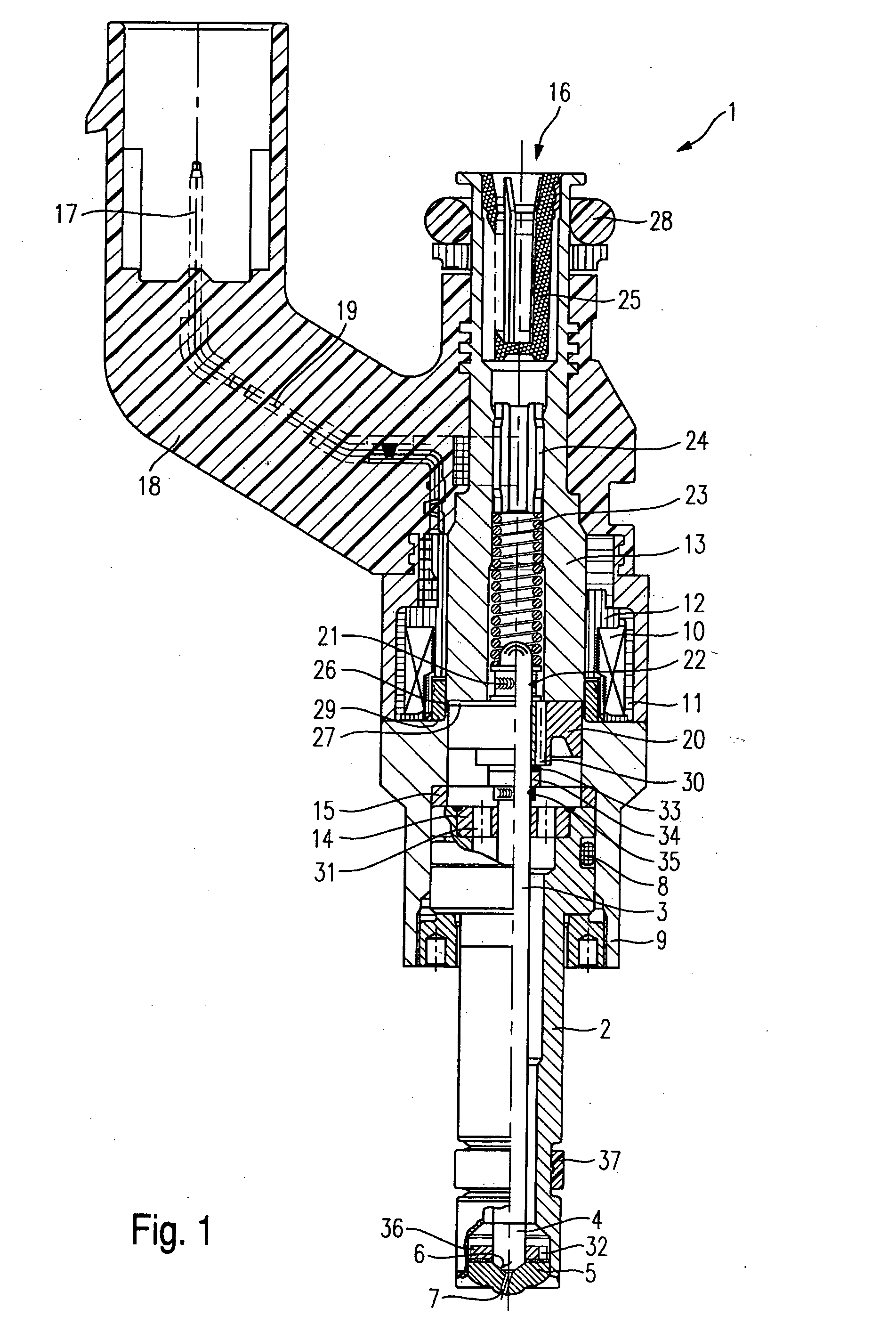
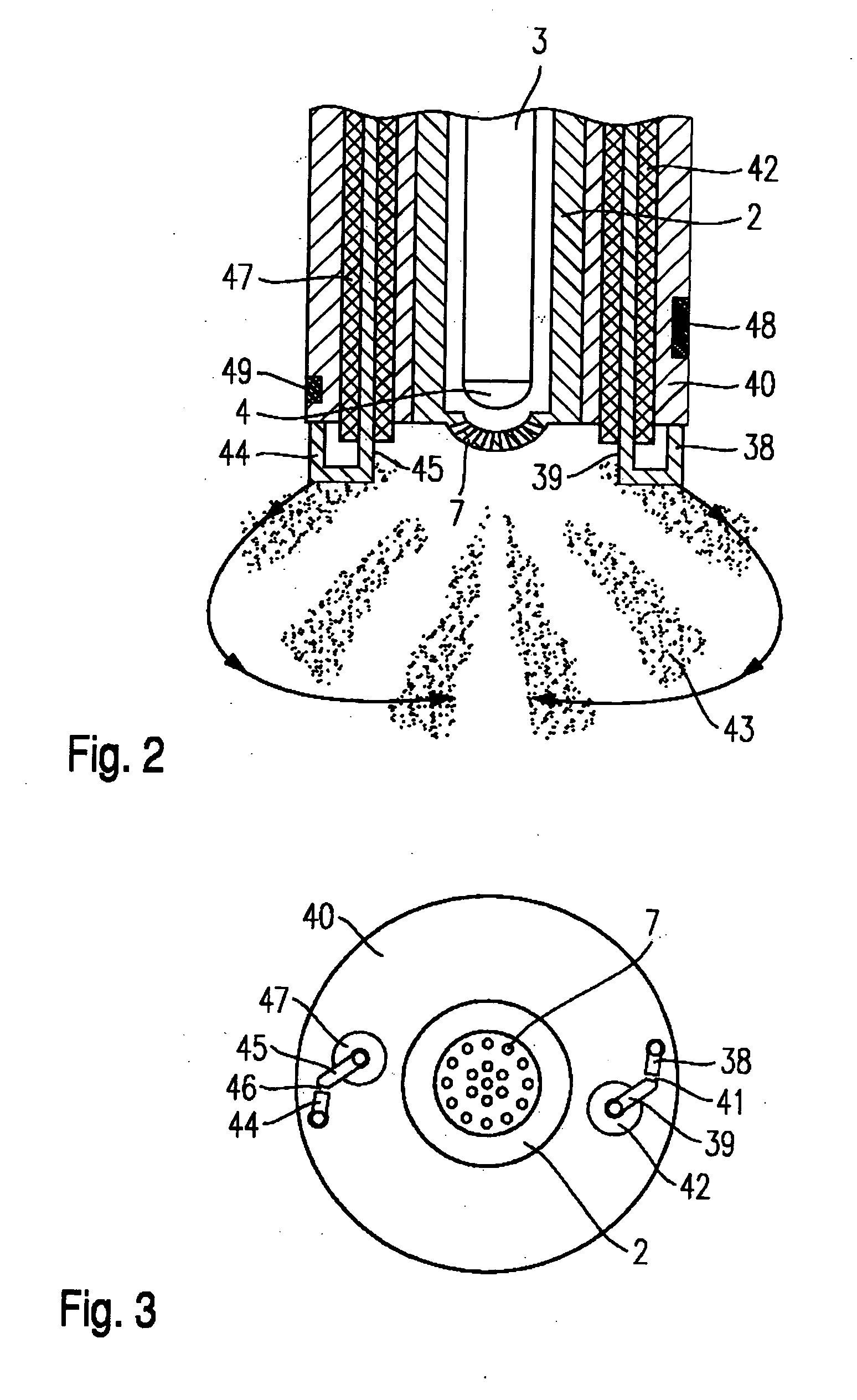
[0005]In an example embodiment, the electrode pairs are positioned in such a way that the spark gaps are distributed evenly about the spray-discharge orifices, and / or the spark gaps are positioned on a circle about the spray-discharge orifices. This provides a uniform ignition of the fuel-air mixture, and the fuel-air mixture may combust evenly and homogenously inside the combustion chamber. The time for the full ignition of the entire fuel-air mixture inside the combustion chamber is minimized.
[0007]Because the length of the spark plug amounts to only 50 to 300 micrometers, the ignition voltage may be selected to be low. In addition, a reduced thickness of the insulating bodies may be chosen.
[0008]Moreover, it is advantageous to integrate a pressure sensor and / or a temperature sensor in the shared housing. This makes it easy to monitor states in the combustion chamber. Furthermore, no additional openings into the combustion chamber, which would be required for external sensors, will be necessary.

Problems solved by technology

Particularly disadvantageous in the fuel injector described in the aforementioned German patent document is that the fuel-air mixture is ignited in only one location in the combustion chamber because of the only one spark gap.
The time for the flame propagation in the combustion chamber is thus increased in a disadvantageous manner.

Method used


Image

  • Fuel Injector Having an Integrated Ignition Device
  • Fuel Injector Having an Integrated Ignition Device
  • Fuel Injector Having an Integrated Ignition Device

Examples


Embodiment Construction

[0012]An exemplary embodiment of the present invention is described in the following by way of example. Identical components have been provided with matching reference numerals.

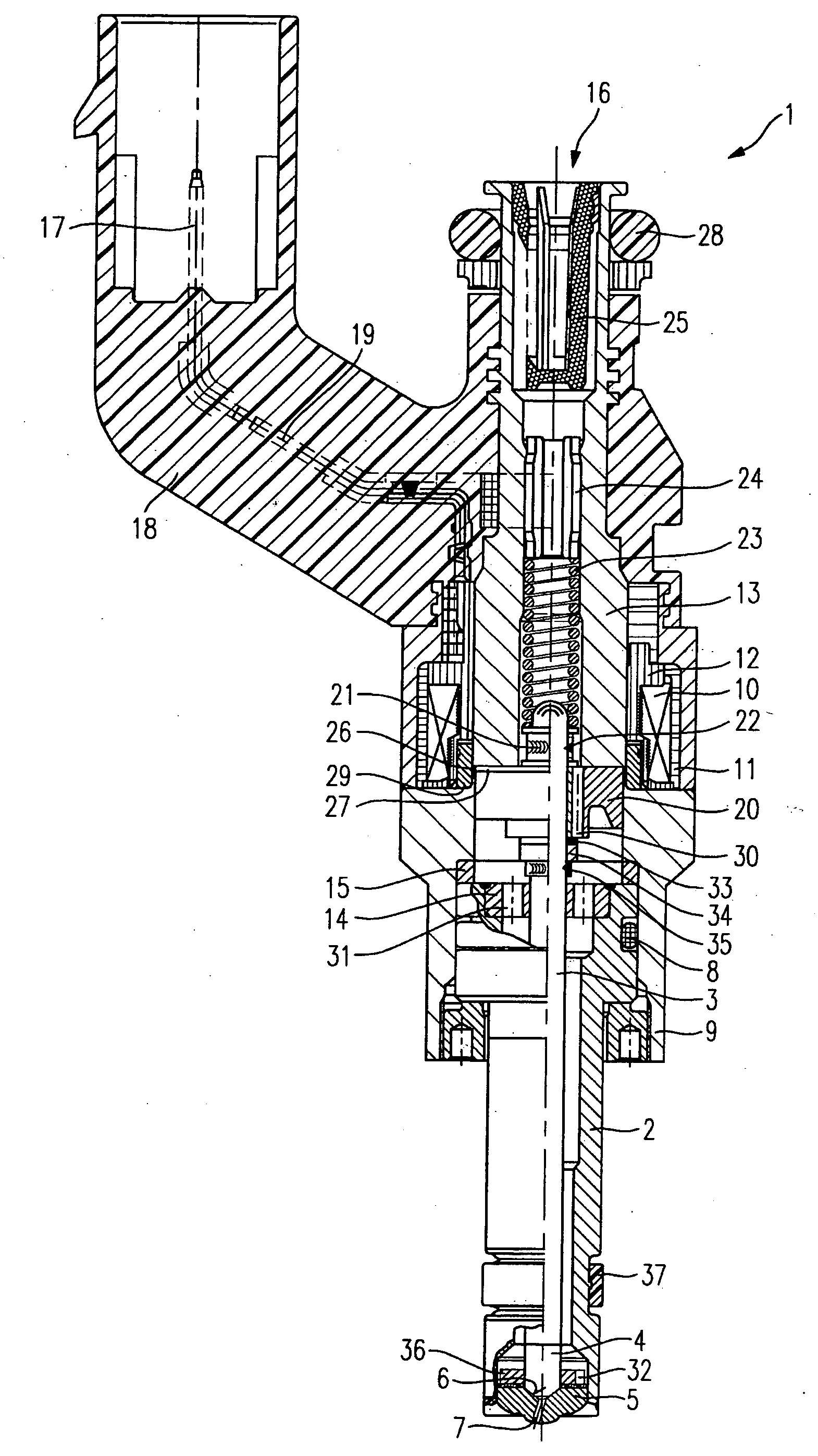
[0013]Before giving a more detailed description of an exemplary embodiment according to the present invention in connection with FIGS. 2 and 3, to provide a better understanding of the present invention, a fuel injector without integrated ignition device shall be explained briefly with reference to FIG. 1.

[0014]An example of a fuel injector 1 lacking an integrated ignition device, shown in FIG. 1, is designed in the form of a fuel injector 1 for fuel-injection systems of mixture-compressing internal combustion engines having externally supplied ignition. Fuel injector 1 is particularly suited for the direct injection of fuel into a combustion chamber (not shown) of an internal combustion engine.

[0015]Fuel injector 1 lacking an integrated ignition device is made up of a nozzle body 2 in which a valve needle 3 ...


PUM


Abstract

A fuel injector having an integrated ignition device includes a first electrode pair for igniting fuel which is injected directly into a combustion chamber of an internal combustion chamber through spray-discharge orifices of the fuel injector. The first electrode pair is made up of a ground electrode and a center electrode which are set apart by a spark gap. The fuel injector and the ignition device are situated in a shared housing. The ignition device has at least one additional spark gap and / or an additional electrode pair.

Description

FIELD OF THE INVENTION[0001]The present invention relates to a fuel injector having an integrated ignition device.BACKGROUND INFORMATION[0002]Published German patent document 102 14 167 describes a fuel injector which has an integrated ignition device. A first electrode and a second electrode form a spark gap on the discharge side of the spray-discharge orifices. One of the advantages of such a fuel injector-spark plug combination is the reduced installation space and the increased flexibility in the combustion-chamber design and the arrangement and sizing of the intake and exhaust valves.[0003]Particularly disadvantageous in the fuel injector described in the aforementioned German patent document is that the fuel-air mixture is ignited in only one location in the combustion chamber because of the only one spark gap. The time for the flame propagation in the combustion chamber is thus increased in a disadvantageous manner.SUMMARY[0004]The fuel injector including an integrated igniti...

Claims


Application Information

Patent Timeline
Patent Type & Authority Applications(United States)
IPC IPC(8): F02M57/06F02M51/06
CPCF02M51/0671F02M2200/24F02M57/06
Inventor VOGEL, MANFREDHERDEN, WERNERECKER, RAINER
Owner ROBERT BOSCH GMBH
Learn More