Supercapacitor charging circuit, charging method and transient wave recording type fault indicator

A technology of supercapacitor and charging circuit, which is applied in the direction of battery disconnection circuit, battery circuit device, collector, etc., which can solve problems such as complex circuit, insufficient system power, unreasonable use of power, etc., and achieve high charging efficiency.

Pending Publication Date: 2017-05-31
威胜电气有限公司
View PDF4 Cites 13 Cited by
  • Summary
  • Abstract
  • Description
  • Claims
  • Application Information

AI Technical Summary

Problems solved by technology

However, the existing technology basically controls the charging current by dividing the resistance into two or more gears. First, the gears are limited, and the charging current cannot be adjusted in real time according to the power provided by the CT (current transformer). The more bits, the more complex the circuit; and for the system powered by the current transformer, whether it uses constant current charging o

Method used


Image

  • Supercapacitor charging circuit, charging method and transient wave recording type fault indicator
  • Supercapacitor charging circuit, charging method and transient wave recording type fault indicator
  • Supercapacitor charging circuit, charging method and transient wave recording type fault indicator

Examples


Embodiment Construction

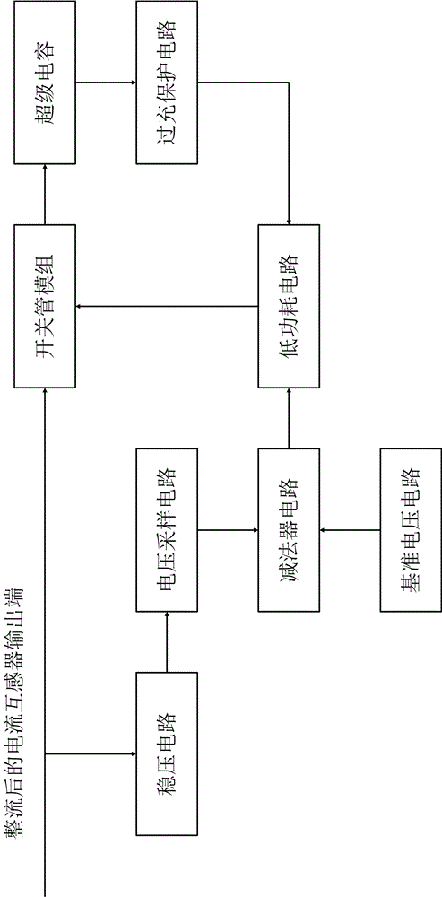
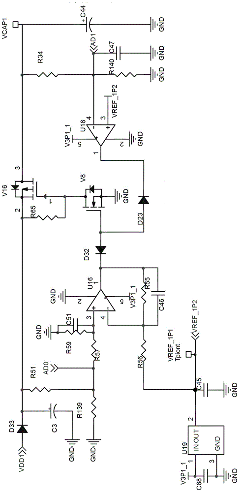
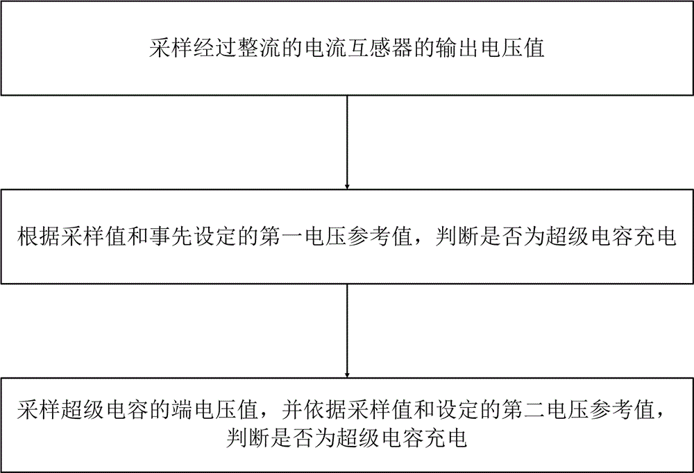
[0031] Such as figure 1 Shown is the functional block diagram of the charging circuit of the present invention: the supercapacitor charging circuit provided by the present invention includes a reference voltage circuit, a voltage sampling circuit, a subtractor circuit, a switching tube module, a voltage stabilizing circuit, and a low power consumption circuit and overcharge protection circuit; the electric energy output by the current transformer is rectified and then connected to the supercapacitor through the switching tube module to charge the supercapacitor; the voltage sampling circuit samples the output voltage of the rectified current transformer, and inputs the sampling signal to the subtractor circuit; the subtractor circuit subtracts the sampling signal from the reference voltage signal provided by the reference voltage circuit to generate a control signal to control the switching on and off of the switch tube module, thereby controlling the charging of the supercapac...


PUM


Abstract

The invention discloses a supercapacitor charging circuit. The supercapacitor charging circuit comprises a reference voltage circuit, a voltage sampling circuit, a subtracter circuit and a switching tube module; a current transformer charges a supercapacitor through the switching tube module; the voltage sampling circuit samples voltage output by the current transformer and inputs the voltage into the subtracter circuit; the subtracter circuit subtracts a reference voltage signal of the reference voltage circuit from a sampling signal to produce a control signal to control work of the switching tube module, so that charging of the supercapacitor is controlled. The invention further discloses a charging method of the supercapacitor charging circuit. The method comprises the following steps: sampling the voltage of the current transformer; judging whether the supercapacitor is needed to be charged according to the voltage sampling value of the current transformer, the voltage sampling value at the supercapacitor end, a first voltage reference value and a second voltage reference value. The invention further discloses a transient wave recording type fault indicator adopting the charging circuit and the charging method. Non-polarized charging of the supercapacitor is realized, charging current is controlled according to the loading capacity of the current transformer, and the charging efficiency is quite high.

Description

technical field [0001] The invention specifically relates to a supercapacitor charging circuit, a charging method and a transient recorder fault indicator thereof. Background technique [0002] With the development of economy and technology and the improvement of people's living standards, there are more and more requirements for uninterrupted power supply of electrical or electronic equipment. As the core technology of uninterrupted power supply, multi-power supply technology has been widely developed and applied. Supercapacitors have been widely favored by people for their advantages such as high power density, long service life, and wide operating temperature range, and have firmly occupied the position of backup power in multi-power supply technology. [0003] There has been a large amount of information on the charging and discharging circuit of supercapacitors. However, the existing technology basically controls the charging current by dividing the resistance into tw...

Claims


Application Information

Patent Timeline
IPC IPC(8): H02J7/00H02J7/34H02J9/04
CPCH02J7/0086H02J7/0031H02J7/345H02J9/04H02J7/00302H02J7/00
Inventor 周到许健李君邓术刘刚
Owner 威胜电气有限公司
Why Eureka
Try Eureka