High-efficiency liquid cooling heat conduction structure and LED lamp

A technology of heat conduction structure and LED lamp, which is applied in cooling/heating devices of lighting devices, cooling/ventilation/heating transformation, semiconductor devices of light-emitting elements, etc. The problem of limited contact surface between coolant and radiator can achieve the effect of increasing contact surface, improving heat exchange efficiency and reducing processing cost

Inactive Publication Date: 2017-05-31
FUJIAN SANAN SINO SCI PHOTOBIOTECH CO LTD
View PDF13 Cites 6 Cited by
  • Summary
  • Abstract
  • Description
  • Claims
  • Application Information

AI Technical Summary

Problems solved by technology

Because the wall surface of the liquid flow channel of the radiator in the prior art is smooth and the contact surface between the cooling liquid and the radiator is limited, the radiator cannot transfer most of the heat generated by the LED lamp to the cooling fluid, resulting in the radiator of the prior art Inefficient thermal conductivity

Method used


Image

  • High-efficiency liquid cooling heat conduction structure and LED lamp
  • High-efficiency liquid cooling heat conduction structure and LED lamp
  • High-efficiency liquid cooling heat conduction structure and LED lamp

Examples


Embodiment 1

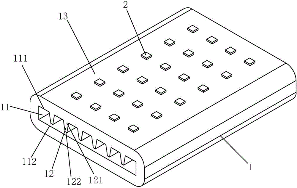
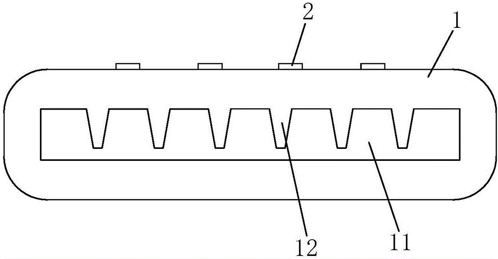
[0027] See figure 1 , figure 2 As shown, a high-efficiency liquid-cooled heat-conducting structure of the present invention includes an integrated radiator 1, which is made of aluminum alloy and has a plate-like structure. The radiator 1 is provided with a liquid flow channel 11 connected at both ends, and the wall surface of the liquid flow channel 11 is provided with a plurality of heat conducting fins 12 at intervals along the direction perpendicular to the flow of the liquid (ie cooling liquid). Each heat conducting fin 12 They are respectively elongated and arranged along the liquid flow direction (that is, the flow direction of the cooling liquid), and the root 121 of each heat conduction fin 12 is integrally formed with the radiator 1, and the tail 122 of each heat conduction fin 12 and the corresponding liquid There is a gap between the wall surface of the flow channel 11 or the opposite heat conducting fins, that is, the tails 122 of each heat conducting fin 12 are ...

Embodiment 2

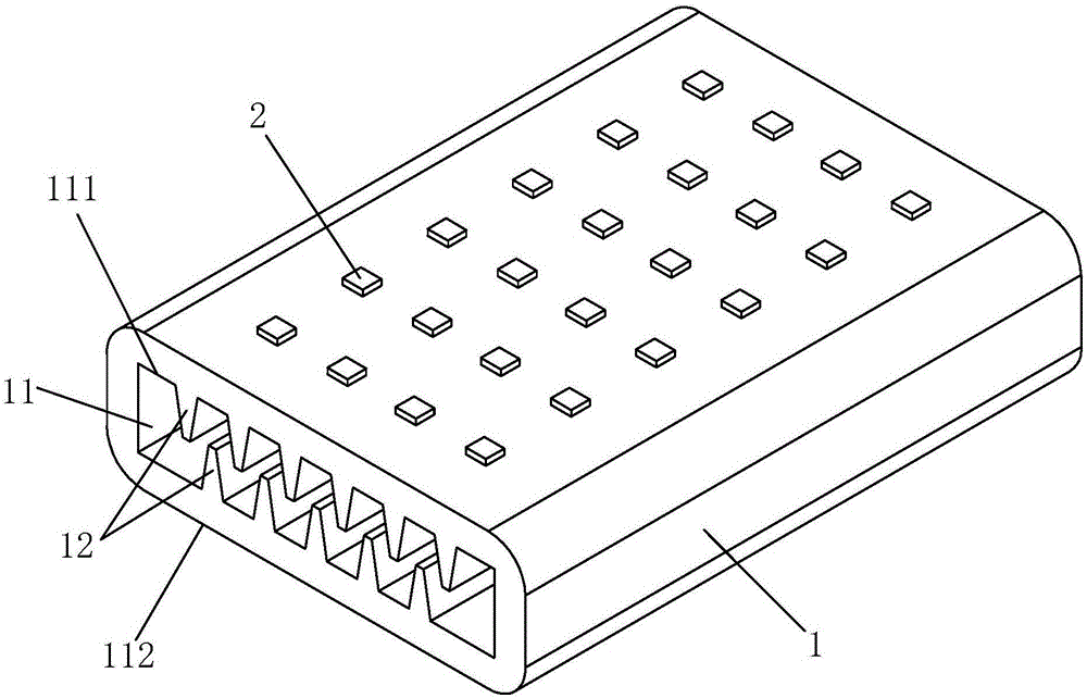
[0035] See image 3 , Figure 4 As shown, the difference between it and Embodiment 1 is that: the two opposite wall surfaces of the liquid flow channel 11 are respectively distributed with the plurality of heat conduction fins 12 at intervals, and the heat conduction fins 12 on the two opposite wall surfaces of the liquid flow channel 11 are in the form of dislocation distribution.

[0036] In this embodiment, the upper wall surface 111 and the lower wall surface 112 of the liquid flow channel 11 are respectively distributed with the plurality of heat conduction fins 12 at intervals, and the heat conduction fins 12 on the upper wall surface 111 and the lower wall surface 112 of the liquid flow channel 11 are misaligned up and down. . Both the upper surface 13 and the lower surface 14 of the heat sink 1 are heat source contact surfaces, and a plurality of LED patch lamps 2 are attached to them respectively. There is a gap between the tails of the heat conducting fins 12 on t...

Embodiment 3

[0039] See Figure 5 , Figure 6 As shown, the difference between it and Embodiment 1 and Embodiment 2 is that the cross section of the liquid flow channel 11 is circular, and the wall surface of the liquid flow channel is distributed with the plurality of heat conduction fins 12 at intervals along the circumference.

[0040] In this embodiment, the heat sink 1 is a strip structure with a square cross-section, and chamfering is done at the four corners. The upper and lower surfaces 13, 14, left and right surfaces 15, 16 of the heat sink 1 are heat source contact surfaces, and a plurality of LED patch lamps 2 are pasted thereon respectively. The direction of the liquid flow channel 11 is along the length direction of the radiator 1 .


PUM


Abstract

The invention discloses a high-efficiency liquid cooling heat conduction structure and a LED lamp. The liquid cooling heat conduction structure comprises a radiator, and the radiator is provided with a flow passage, heat conduction fins are distributed in wall spacing of the flow passage and are respectively arranged along liquid flow direction, the heat conduction fins and the radiator are formed in whole, there is a gap between the heat conduction fins and the opposite wall surface of the flow passage or and the opposite heat conduction fins. The LED lamp comprises the high-efficiency liquid cooling heat conduction structure, and one or various heat source in the LED lamp are fixed on the radiator. Cooling liquid flow in the flow passage, contact surface of cooling liquid and the radiator is greatly increased, thus efficiency of heat exchange of cooling liquid and the radiator is greatly increased, radiating efficiency of the LED lamp is improved.

Description

technical field [0001] The invention relates to a heat conduction structure, in particular to an efficient liquid-cooled heat conduction structure and an LED lamp. Background technique [0002] Some high-power LED lamps in the prior art use a liquid-cooled heat sink to dissipate heat. The radiator of the liquid-cooled heat sink is provided with a liquid flow channel. When the cooling liquid (such as cold water) flows in the liquid flow channel, it communicates with the radiator. The incoming heat completes the heat exchange, and takes away the heat through discharge, so as to achieve the effect of cooling the high-power LED lamp. Because the wall surface of the liquid flow channel of the radiator in the prior art is smooth and the contact surface between the cooling liquid and the radiator is limited, the radiator cannot transfer most of the heat generated by the LED lamp to the cooling fluid, resulting in the radiator of the prior art Inefficient heat transfer. Contents ...

Claims


Application Information

Patent Timeline
Patent Type & Authority Applications(China)
IPC IPC(8): H05K7/20F21V29/56F21Y115/10
CPCF21V29/56H05K7/20218
Inventor 伍婵娟
Owner FUJIAN SANAN SINO SCI PHOTOBIOTECH CO LTD
Why Eureka
Try Eureka