Intraoral coil for high-resolution intracranial artery imaging

A high-resolution, intraoral technology, applied in the fields of application, medical science, telemetry patient monitoring, etc., can solve problems such as shortage, achieve the effect of improving efficiency, less discomfort for patients, and improving the quality of parallel imaging

Pending Publication Date: 2017-06-06
娄昕
View PDF1 Cites 0 Cited by
  • Summary
  • Abstract
  • Description
  • Claims
  • Application Information

AI Technical Summary

Problems solved by technology

[0004] Therefore, for the imaging of intracranial arteries, there is still a lack of local coils that can be easily and quickly placed in the patient's body, making the patient feel comfortable, and at the same time ensuring the integrity and clarity of the imaging.

Method used


Image

  • Intraoral coil for high-resolution intracranial artery imaging
  • Intraoral coil for high-resolution intracranial artery imaging
  • Intraoral coil for high-resolution intracranial artery imaging

Examples


Embodiment 1

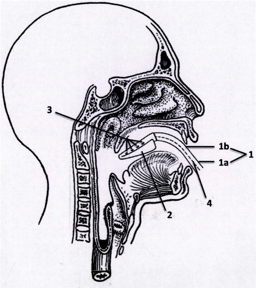
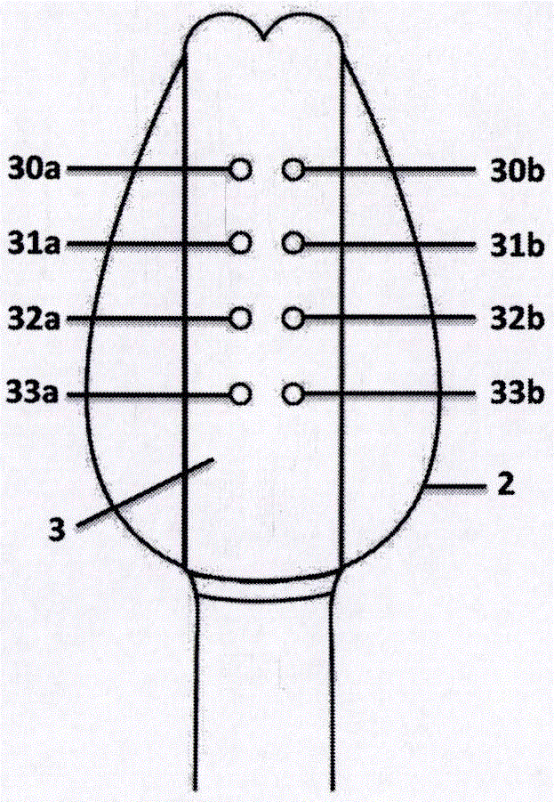
[0032] Such as figure 1 As shown, an intraoral coil for high-resolution imaging of intracranial arteries includes a handle 1, a flexible housing 2, a receiving coil unit 3, and a transmission device 4 for transmitting received magnetic resonance signals and / or data, The handle 1 includes a grip end 1a and a connecting piece 1b, the gripping end 1a is a hand-held part for the doctor to operate and position, the handle 1 is connected to the flexible housing 2 through the connecting piece 1b, the The receiving coil unit 3 is arranged on the flexible housing 2, the receiving coil unit 3 includes at least three sets of receiving coils, one end of the transmission device 4 is connected to the receiving coil, and the other end of the transmission device 4 It is connected with an external receiving device, and transmits the magnetic resonance signal and / or data received by the receiving coil unit 3 to the external receiving device. The intraoral coil of the present invention is used ...

Embodiment 2

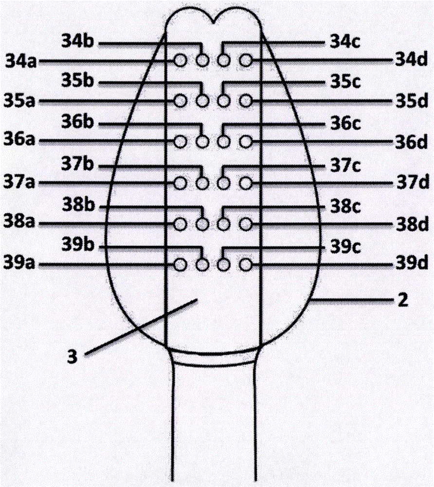
[0040] The difference between this embodiment and Embodiment 1 is that: image 3 As shown, on the basis of Embodiment 1, according to different graphic acquisition requirements, the receiving coil unit 3 includes six groups of receiving coils 34, 35, 36, 37, 38, 39 or 8 groups of receiving coils, and each group receives The coil consists of four receiving coils (34a, 34b, 34c, 34d / 35a, 35b, 35c, 35d / 36a, 36b, 36c, 36d / 37a, 37b, 37c, 37d / 38a, 38b, 38c, 38d / 39a, 39b, 39c, 39d), the receiving coil can also be saddle-shaped.

[0041] Such as Figure 5 As shown, the handle 1 is connected to the proximal end of the receiving coil unit 3 provided on the flexible housing 2 through the connecting piece, and the proximal end refers to the end close to the operator.

[0042] Such as Figure 1-5 As shown, through the arrangement of the above-mentioned receiving coils, the signal acquisition of the intracranial segment of the internal carotid artery and its branches, the anterior cerebr...


PUM


Abstract

The invention relates to an intraoral coil for high-resolution intracranial artery imaging. The intraoral coil comprises a handle, a flexible housing, a receiving coil unit, and a transmission device for transmitting the received magnetic resonance signal and / or data, the handle comprises a grip end and a connector, the handle is connected to the flexible housing through the connector, the grid end is a handheld portion for doctors to perform operation and positioning, the receiving coil unit is arranged on the flexible housing and comprises at least three sets of receiving coils, one end of the transmission device is connected with the receiving coils, and the other end of the transmission device is connected to an external receiving device. The intraoral coil is used for imaging head blood vessels via the oropharynx, especially the vertebral basilar artery, the unique oral ergonomic three-dimensional surface design is adopted, the intraoral coil can be easily put in the oral cavity of a patient easily and quickly, efficiency in examination is improved, the head blood vessel structure can be observed directly and clearly, and integrity and clearness in imaging are assured.

Description

technical field [0001] The invention relates to a magnetic resonance imaging system, in particular to an intraoral coil for high-resolution imaging of intracranial arteries. The intraoral coil is clinically used for magnetic resonance imaging inspection of intracranial artery walls. Background technique [0002] Medical Magnetic Resonance Imaging (MRI) system equipment usually includes a superconducting magnet that generates a stable basic magnetic field, a gradient coil that generates a gradient magnetic field, and various radio frequency devices (hereinafter referred to as radio frequency coils). Superconducting magnets and gradient coils are generally designed in a cylindrical shape concentrically arranged around the patient acquisition cavity, which is permanently installed in the MRI scanner to generate gradient magnetic fields. Radio frequency coils are used to transmit and receive radio frequency pulses to excite nuclei to emit magnetic resonance signals and / or to acq...

Claims


Application Information

Patent Timeline
IPC IPC(8): A61B5/055
CPCA61B5/0042A61B5/055A61B2562/02
Inventor 娄昕马林王婷徐正扬
Owner 娄昕
Why Eureka
Try Eureka