Passive remote center compliance device

A compliant and passive technology, applied in the direction of manipulators, joints, program-controlled manipulators, etc., can solve the problems of small axial force, limit the compliant range of compliant devices, and difficulty in ensuring performance consistency, and achieve easy replacement, good decoupling, and Effects that are easy to adjust

Active Publication Date: 2017-06-06
TIANJIN POLYTECHNIC UNIV
View PDF4 Cites 6 Cited by
  • Summary
  • Abstract
  • Description
  • Claims
  • Application Information

AI Technical Summary

Problems solved by technology

However, due to the nonlinear characteristics of the ESP elastic member itself and the difficulty in ensuring the consistency of all product performance in ESP production, the compliance performance of the passive compliance mechanism has been affected to a certain extent; at the same time, the axial force that the passive compliance mechanism can withstand Small, unable to complete installation tasks requiring large axial force
U.S. Patent 67926899B2 proposes to add an axial limit rod to provide and bear the axial force after the initial compliance alignment; but the existence of the limit rod limits the compliance range of the compliance device, making the device only suitable for compliance Assembly work with small scope requirements

Method used


Image

  • Passive remote center compliance device
  • Passive remote center compliance device
  • Passive remote center compliance device

Examples


Embodiment Construction

[0013] Specific embodiments of the present invention are given below. The specific embodiments are only used to further describe the present invention in detail, and do not limit the protection scope of the claims of this application.

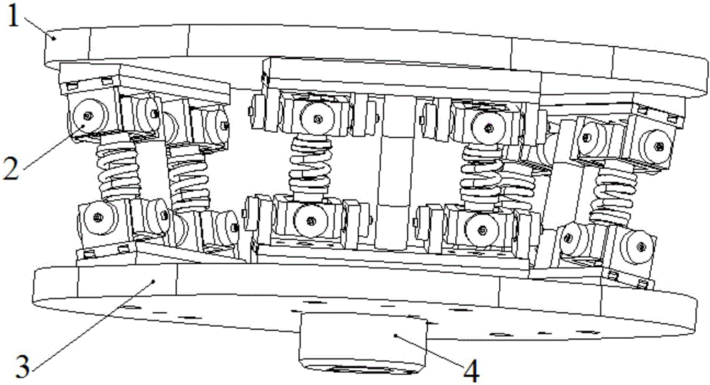
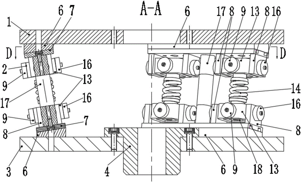
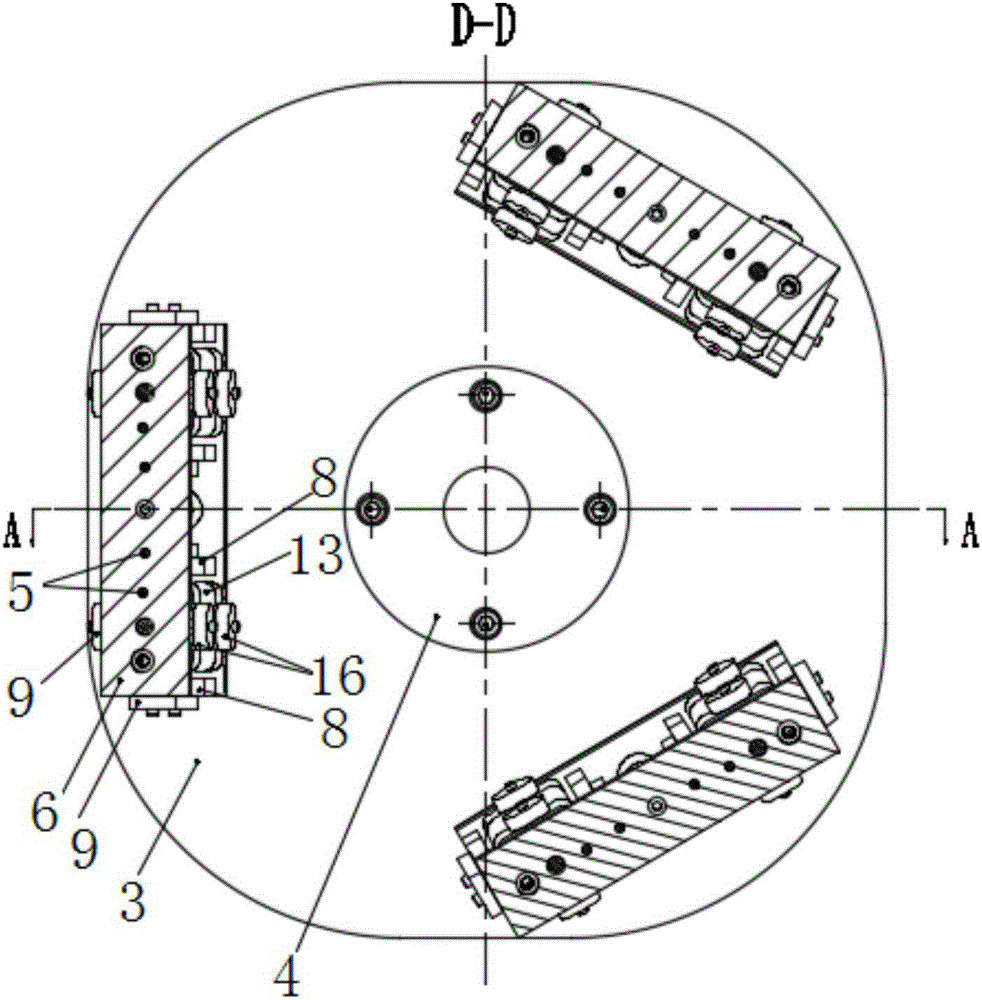
[0014] The present invention provides a passive compliance device (see Figure 1-3 , Referred to as device), including an upper connecting plate 1, three sets of elastic component units 2, a lower connecting plate 3 and a flange connecting block 4;

[0015] The upper surface of the upper connecting plate 1 is designed with a flange connection port, which is used to connect the end of the actuator such as the end of the robot arm to drive the passive compliant device to complete the assembly task; the flange connection block 4 is installed on the end of the hexagonal screw On the lower connecting plate 3, the flange connecting block 4 is used to connect a clamping device such as a three-jaw chuck to clamp the parts to be installed; three groups of e...


PUM


Abstract

The invention discloses a passive remote center compliance device. The passive remote center compliance device comprises an upper connecting plate, three sets of elastic assembly units, a lower connecting plate and a flange connecting block; a flange connecting port is formed on the upper surface of the upper connecting plate; the flange connecting block is arranged on the lower connecting plate; the three sets of elastic assembly units are uniformly arranged between the upper connecting plate and the lower connecting plate; each elastic assembly unit comprises positioning pins, two inclination angle connecting plates, two base plates, a set of rubber spring units and two sets of compression spring units; and each compression spring unit comprises an upper section connected to the upper connecting plate, a lower section connected to the lower connecting plate and a compression spring assembly, wherein the upper section and the lower section are identical in structure, and the upper section comprises a right-handed torsion spring, a rotating shaft, an external rotation frame, a left-handed torsion spring and an internal rotation frame. The passive remote center compliance device has the advantages that the compliance range is wide, the decoupling performance is good, and elastic elements and intermediate connecting parts can be replaced conveniently so as to adjust the shearing rigidity, the bending rigidity and the compliance center position.

Description

Technical field [0001] The invention relates to an automatic assembly device, in particular to a passive compliance device. Background technique [0002] With the development of industrial automation, automatic assembly has been widely used in industrial production, and automatic assembly of shaft and hole parts is the main one. Assembly robots used for automatic assembly are a type of industrial robots, which are different from ordinary industrial robots. The ends of assembly robots are equipped with compliant devices. Passive compliance devices are widely used in industrial production due to their convenience, large compliance range, and low requirements for robot control systems. The most widely used passive compliance mechanism today is RCC (Remote Center Compliance). US Patent 4,098,001 uses a metal elastic element as an elastic body to connect between the upper and lower platforms. According to the different installation and distribution modes of the elastic element, the ...

Claims


Application Information

Patent Timeline
IPC IPC(8): B25J9/00B25J9/08B25J17/00
CPCB25J9/003B25J9/08B25J17/00Y02E30/30
Inventor 戚江波何薇肖军娜
Owner TIANJIN POLYTECHNIC UNIV
Why Eureka
Try Eureka