
Method and equipment for eliminating visual blindness of motor vehicle driver

A technology for motor vehicles and visual blind spots, applied in the field of auto parts, can solve problems such as unintuitive, increase safety hazards, and high cost, and achieve the effects of simple structure, convenient installation, and low heat generation

Inactive Publication Date: 2017-06-06
曾令鹏
View PDF4 Cites 13 Cited by
  • Summary
  • Abstract
  • Description
  • Claims
  • Application Information

AI Technical Summary

Problems solved by technology

At present, the way to solve the visual blind spot of motor vehicle drivers in the market is mainly to take images of the driver's blind spot through the camera, and through processing and calculation, scale them in proportion to the vehicle's central control display or an additional display for display, such as parking Auxiliary imaging system or vehicle 360° imaging system, the main disadvantage of this technical solution is: the driver of the motor vehicle needs to observe the central control display screen or the additional display screen, which distracts the driver's attention and increases potential safety hazards; the displayed image Information is scaled down, but still not intuitive
In addition, in the prior art, there is a solution to process the driver’s visual blind spot image captured by the camera and project it on the surface of the car component by using a projection device, but the cost of this technical solution is relatively high, and the system is relatively complicated, and additional components need to be designed in the vehicle. The installation point of the projection device, and the projection device will generate strong light and heat, which will accelerate the light and heat aging of the surrounding components, and the cooling of the projection device will also increase the noise source in the car

Method used


Image

  • Method and equipment for eliminating visual blindness of motor vehicle driver
  • Method and equipment for eliminating visual blindness of motor vehicle driver
  • Method and equipment for eliminating visual blindness of motor vehicle driver

Examples


Embodiment

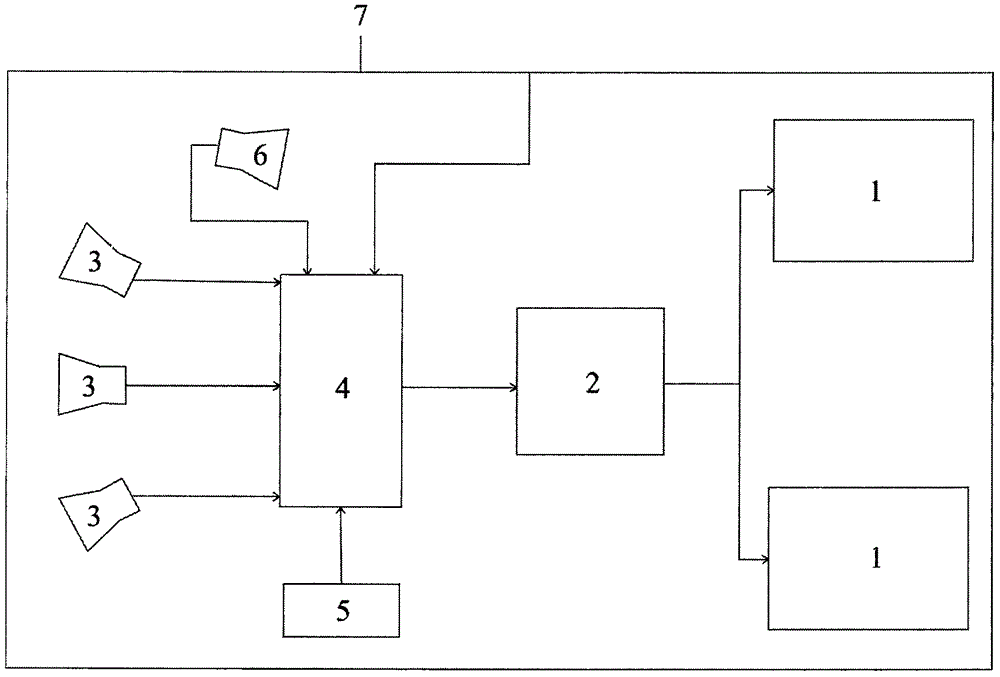
[0023] Such as figure 1 As shown, a device for eliminating the visual blind spot of a motor vehicle driver includes: a flexible transparent display screen 1 installed on a component blocking the driver's line of sight in the cockpit of a motor vehicle, and a driving backplane 2 connected to the flexible transparent display screen 1 1. One or more cameras 3 for capturing images in the visual blind zone of the motor vehicle driver, an image processing controller 4 and a power supply 5 connected between the cameras 3 and the driving backplane 2 .

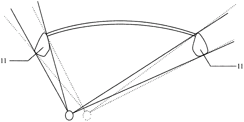
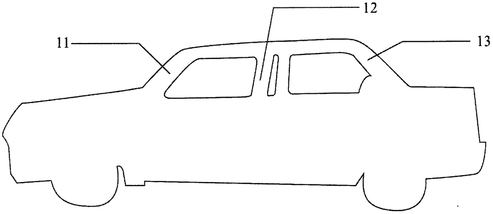
[0024] Such as figure 2 As shown, the A-pillars 11 on the left and right sides in the cockpit of the motor vehicle block the driver's line of sight, and as the position of the driver's eyeballs changes, the angle and range of the visual blind zone images blocked by the A-pillars 11 will also change. The motor vehicle cockpit is provided with a camera sensor 6 that detects the driver's eyeball position, and the camera sensor 6 is conn...


PUM


Abstract

The invention discloses a method for eliminating the visual blindness of motor vehicle driver. The method includes that a flexible transparent display screen is installed on the component which blocks the line of sight of the driver in the cockpit of motor vehicle; the image of the visual blindness which is blocked in the line of sight of driver is displayed in the flexible transparent display screen which is connected with an image processing controller and a camera; the information of the image of the visual blindness is obtained through one or multiple cameras arranged on the motor vehicle; the image information is addressed through the image processing controller to be connected with the view of the driver, so as to be sent to the flexible transparent display screen to display. In addition, the invention also discloses an equipment for eliminating the visual blindness of motor vehicle driver. The flexible transparent display screen has the advantages of simple structure, being convenient to install, small calorific power, do not needing to design and install the structure and the cooling system, do not affecting the previous visual effect of the vehicle, the space in the vehicle and the environment in the vehicle, being capable of displaying the whole CAN(Controller Area Network) information, being convenient for the driver to acquire the driving information and assisting the driver to make driving judgement.

Description

technical field [0001] The invention relates to the technical field of auto parts, in particular to a method and equipment for eliminating visual blind spots of motor vehicle drivers. Background technique [0002] Due to the limitations of the inherent structural design of the motor vehicle, when the driver of the motor vehicle sits in the driving position, part of his vision will be blocked by the inherent components of the motor vehicle, forming a blind spot for the driver's vision. At present, the way to solve the visual blind spot of motor vehicle drivers in the market is mainly to take images of the driver's blind spot through the camera, and through processing and calculation, scale them in proportion to the vehicle's central control display or an additional display for display, such as parking Auxiliary imaging system or vehicle 360° imaging system, the main disadvantage of this technical solution is: the driver of the motor vehicle needs to observe the central contro...

Claims


Application Information

Patent Timeline
Patent Type & Authority Applications(China)
IPC IPC(8): B60R1/00
CPCB60R1/00B60R2300/8026B60R2300/8073
Inventor 曾令鹏
Owner 曾令鹏
Learn More