Power-driven tilt three-rotor unmanned aerial vehicle

A technology of three-rotor and unmanned aerial vehicle, applied in the field of unmanned aerial vehicles, can solve the problems of small radius maneuvering and hovering, small payload, slow cruising speed, etc., and achieve the effect of improving flight efficiency and applicability

Inactive Publication Date: 2017-06-06
AVIC GUIZHOU AIRPLANE
View PDF5 Cites 28 Cited by
  • Summary
  • Abstract
  • Description
  • Claims
  • Application Information

AI Technical Summary

Problems solved by technology

Most of the fixed-wing UAVs use the runway to take off and land, which has the advantages of large payload, fast cruise speed, long endurance and high efficiency, but it is highly dependent on the runway and cannot maneuver or hover in a small radius. , which limits its use
Rotor-wing UAVs include ordinary helicopters and multi-rotor UAVs. They can take off and land vertically, and can fly in a smaller space. Their flexibility is higher than that of fixed-wing UAVs. However, their There are disadvantages of small payload, slow cruising speed and short battery life
Therefore, both UAVs have their own advantages and disadvantages, which limit their flexibility and efficiency to a certain extent.

Method used


Image

  • Power-driven tilt three-rotor unmanned aerial vehicle
  • Power-driven tilt three-rotor unmanned aerial vehicle
  • Power-driven tilt three-rotor unmanned aerial vehicle

Examples


Embodiment Construction

[0018] The specific embodiment of the present invention is described below in conjunction with accompanying drawing:

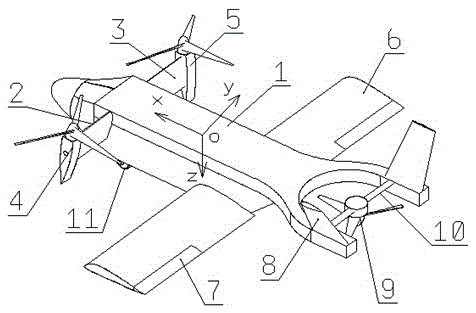
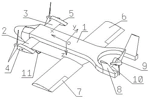
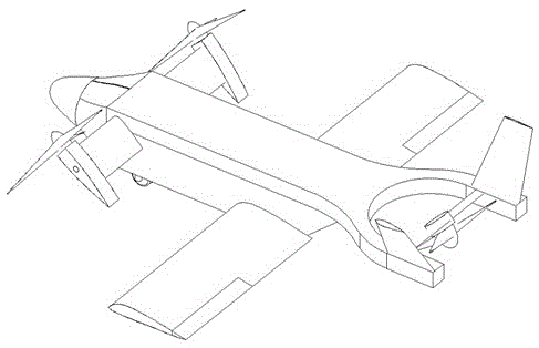
[0019] An electric tilting three-rotor drone, comprising a fuselage 1, a main wing 6, an aileron 7, a landing gear 11, a left canard 2, a right canard 3, a left motor rotor 4, a right motor rotor 5, a fixed V-shaped Empennage 8, rear motor rotor 9 and rear motor support rotating shaft 10, main wing 6 is installed in fuselage 1 middle part, landing gear 11 is arranged on fuselage 1 bottom, aileron 7 is arranged on main wing 6 rear outside, left canard 2 and right The canard 3 is connected to the fuselage 1 through rotary pumping, the left motor rotor 4 and the right motor rotor 5 are respectively fixed on the wingtips of the left canard 2 and the right canard 3, and the fixed V-shaped tail 8 is installed on the tail of the fuselage 1 Above, the rear motor rotor 9 is fixed and installed between the V-shaped tail 8 through the rear motor support shaft 10, the lef...


PUM


Abstract

The invention provides a power-driven tilt three-rotor unmanned aerial vehicle. The power-driven tilt three-rotator unmanned aerial vehicle has flight characteristics of both a helicopter and a fixed-wing aircraft and can take off and land in a vertical and short-distance way. The integral structure of the power-driven tilt three-rotor unmanned aerial vehicle is composed of all-moving canard wings, straight low wings and a fixed V tail. Two motors and rotors of the unmanned aerial vehicle are fixed at the wing tips of the canard wings and can independently tilt by certain angles along with the canard wings, and another motor and rotor of the unmanned aerial vehicle are installed in the V tail and can tilt by certain angles around a rotating shaft. When the rotating shafts of the thee rotors of the unmanned aerial vehicle tilt to a position near a Z axis, the unmanned aerial vehicle can fly like the helicopter; and when the thee rotors tilt to a position near an X axis, the unmanned aerial vehicle can fly like the fixed-wing aircraft. Through simultaneous control of the thrust and directions of the thee rotors, the reaction torque of the rotors is overcome and the posture of the unmanned aerial vehicle is controlled. The unmanned aerial vehicle provided by the invention can take off and land in a limited place or runway to execute special tasks and is improved in flight speed, duration of flight and payload.

Description

technical field [0001] The invention relates to the field of unmanned aerial vehicles, in particular to a tilt-rotor unmanned aerial vehicle capable of vertical / short take-off and landing. Background technique [0002] At present, UAV technology has been widely used in our lives, such as aerial photography, inspection, investigation, entertainment and so on. The UAVs on the market are mainly divided into two categories: fixed-wing UAVs and rotary-wing UAVs. Most of the fixed-wing UAVs use the runway to take off and land, which has the advantages of large payload, fast cruise speed, long endurance and high efficiency, but it is highly dependent on the runway and cannot maneuver or hover in a small radius. , which limits its usage. Rotor-wing UAVs include ordinary helicopters and multi-rotor UAVs. They can take off and land vertically, and can fly in a smaller space. Their flexibility is higher than that of fixed-wing UAVs. However, their It has the disadvantages of small p...

Claims


Application Information

Patent Timeline
Patent Type & Authority Applications(China)
IPC IPC(8): B64C27/26B64C27/28B64C29/00B64C39/12
CPCB64C27/26B64C27/28B64C29/0033B64C39/12B64U70/80B64U30/20
Inventor 班韬泽韦毅刘健陈惠惠王雪峰袁云李支强
Owner AVIC GUIZHOU AIRPLANE
Why Eureka
Try Eureka