Riverway floating object recovery and treatment method

A technology for recycling and disposing of floating objects, which is applied to the cleaning of open water surfaces, water conservancy projects, construction, etc., to solve problems such as the inability to salvage floating objects, increase the workload of cleaning machines, and increase the intensity of manual work, so as to avoid sudden The effect of dropping, increasing the cleaning range, and increasing the number of grabs

Inactive Publication Date: 2017-06-06
重庆文达和科技有限公司
View PDF0 Cites 3 Cited by
  • Summary
  • Abstract
  • Description
  • Claims
  • Application Information

AI Technical Summary

Problems solved by technology

[0003] Most of the two types of cleaning machines are fixed in front of the water inlet of the riverbed hydropower station to facilitate the cleaning of floating objects on the water surface; but near the riverbed water inlet, the two types of cleaning machines are unable to salvage the floating objects And, especially when the gate is opened, the water flow speed at the water inlet of the riverbed hydropower station is accelerated, which makes the efficiency of the cleaning machine low when salvaging, and the floating objects on the water surface will quickly flow into the riverbed water inlet with the water flow, forming floating objects to block The impact of the door slot of the water building will cause damage to the main body of the water retaining building; when realizing the opening and closing of the lower claw, the hydraulic method is generally used to realize the movement of the lower claw, and the small cleaning machine uses a steel rope to move the lower claw. The rake claws are pulled to realize the movement of the lower rake claws. Both methods have their own advantages, but the hydraulic starting method itself has a large weight, which increases the working load of the cleaning machine, while the steel rope manual pulling method has its own advantages. When encountering a large number of floating objects, the intensity of manual work is greatly increased and the efficiency is low

Method used


Image

  • Riverway floating object recovery and treatment method
  • Riverway floating object recovery and treatment method

Examples


Embodiment 1

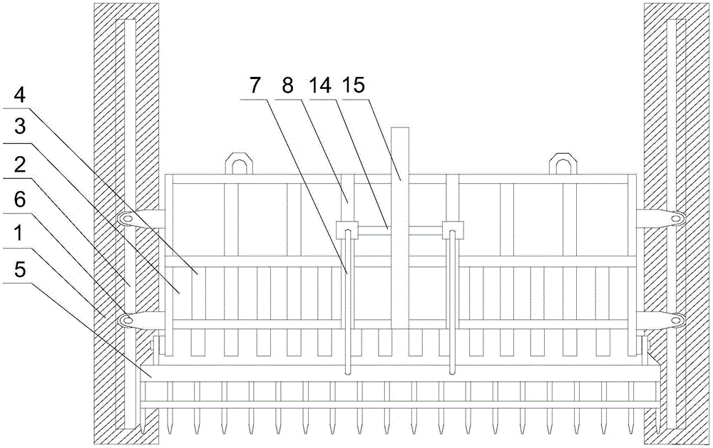
[0026] Such as figure 1 and figure 2 Shown, the present invention comprises the following steps:

[0027] A Start the hydraulic cylinder, and the jacking rod drives the support column to move forward under the push of the output end of the hydraulic cylinder to expand the cleaning range;

[0028] The B fence body moves up and down quickly in the groove of the guide rail under the traction of the connecting rod. Manually adjust the screw rod, which cooperates with the threaded through hole, so that the moving block moves on the connecting rod, and the moving block is driven by the connecting rod. The lower rake claws are opened, and the fence body moves down into the water;

[0029] C. The upper claw blocks the floating object to prevent it from moving further, and reversely rotates the screw rod, so that the lower claw automatically moves down, and cooperates with the upper claw to clamp the floating object. Finally, under the traction of the connecting rod, the fence body ...

Embodiment 2

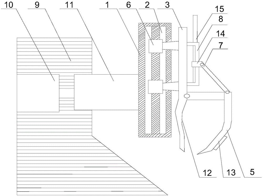
[0032] Such as figure 2 As shown, this embodiment is based on Embodiment 1. The upper claw 4 is provided with a detour 12 whose bending direction is opposite to that of the lower claw 5 , and the detour 12 is located below the fence body 3 . The detour 12 on the upper claw 4 can increase the inner area of ​​the annular clamping space formed by the upper claw 4 and the lower claw 5. When the upper claw 4 penetrates into the water surface, the floating object will be blocked to prevent it from continuing to move. The claw 5 clamps the floating objects under the action of its own gravity, and while preventing the floating objects from falling off each time it is grabbed, it can also greatly increase the number of grabs and improve the collection efficiency.

Embodiment 3

[0034] Such as figure 1 As shown, this embodiment is based on Embodiment 1, and a counterweight 13 is installed at the end of the lower claw 5 . When the number of grabs is large or the volume of the floating object itself is large, and the gravity effect of the lower claw 5 itself is not enough to hold the floating object stably, the counterweight 13 arranged at the end of the lower claw 5 can indirectly increase the weight of the lower claw 5. The clamping strength of the rake claws 5 on the floating objects, and the lower rake claws 5 are hingedly connected with the fence body 3. Under the action of manual adjustment of the steel rope, the grabbing efficiency can be ensured each time, and at the same time, the captured floating objects can be prevented from falling on the fence body 3. Falling suddenly while rising.

[0035] Further, preferably, the angle at which the lower claws 5 move up and down is 0° to 110°. The movable angle of the lower rake claw 5 is set in the ra...


PUM


Abstract

The invention discloses a riverway floating object recovery and treatment method. The riverway floating object recovery and treatment method comprises the following steps that a hydraulic cylinder is started, and a jacking rod drives a supporting pillar to move forwards under pushing of the output end of the hydraulic cylinder; a fence body quickly moves up and down in a guide rail groove under the traction of a connection rod, a screw rod is manually adjusted, a movable block can move on the connection rod, a movable block makes a lower raking pawl to open under driving of the connection rod, and the fence body moves downwards into the water; an upper raking pawl blocks floating objects to prevent the floating objects from continuous moving, the screw rod is reversely rotated, and the lower raking pawl automatically moves downwards and is matched with the upper raking pawl so as to hold the floating objects; and finally, the fence body is overall lifted under traction of the connection rod, and the collected floating objects are stacked to a fixed treatment site. When opening and closing of the lower baking pawl are adjusted, one screw rod is adopted to be matched with the movable block; opening and closing of the lower baking pawl can be achieved by forward and reversely rotating the screw rod; and it is obtained by calculation that 17 times power can be saved for adjusting the screw rod, and the work difficulty of opening and closing of lower raking pawl is lowered.

Description

technical field [0001] The invention relates to a sewage cleaning structure of a hydropower station, in particular to a method for recycling and treating floating objects in a river course. Background technique [0002] In reservoirs or rivers with a lot of sewage, in order to ensure the safe and normal operation of hydropower stations or pumping stations, it is often necessary to install sewage cleaning equipment so that the sewage can be cleaned without shutting down or emptying the reservoir. At present, small hydropower stations generally rely on manual cleaning. Most low-head and high-flow power stations, due to untimely cleaning, make the water pressure difference between the front and rear of the trash rack greatly exceed the design standard. Shutdown during the flood season for cleaning and safe operation of the trash rack It becomes a problem during power generation in flood season; while large-scale hydropower stations use bucket cleaning machines or rotary cleanin...

Claims


Application Information

Patent Timeline
Patent Type & Authority Applications(China)
IPC IPC(8): E02B15/10E02B15/06
CPCE02B15/06E02B15/10
Inventor 向美友
Owner 重庆文达和科技有限公司
Why Eureka
Try Eureka